
Abstract
This paper presents a detailed comparative study of centralized mobility management and distributed mobility management. This paper also surveys the current issues in centralized mobility management and discusses the related work of distributed mobility management approach. We provide the proposed distributed mobility management scheme by using a novel architectural element named location management mobility routing anchor (LMMRA). The LMMRA supports both location management and dynamic distributed mobility routing functionalities. Our approach overcomes some of the major limitations of centralized IP mobility management solutions, such as well-known network bottleneck, scalability, and single point of failures.
Access provided by Autonomous University of Puebla. Download conference paper PDF
Keywords
1 Introduction
With the increasing volumes of mobile data traffics and massive increase in the number of interconnected devices, especially on demand for “imperceptible latency” with Tactile Internet, and demand millisecond-level latency and nearly 100 % reliability with Internet of Thing service [1]. However, current existing IP mobility solutions, has adopted a centralized approach and often hierarchical architecture, generally introduce an anchor point in the core network, e.g., HA in MIPv6 [2], LMA in PMIPv6 [3], GGSN/PGW in 3GPP [4, 5]. Yet in a flat architecture, the traffic anchor point can be much lower (e.g., located in the access system) compared with centralized architecture. Even though the currently centralized network architecture is IP-based mobility, all of the user data packets will be tunneled to the core network entities, where the user data packets are encapsulated between centralized mobility entities. During handovers, tunnel updates in the core network may impact on the overall efficiency by introducing delays and packet loss. Furthermore, the current centralized approaches to mobility management have some problems and limitations which are single point of failure and bottleneck, nonoptimal routing path, scalability problem, long handover delay, e.g. [6, 7].
To solve these problems, IMT-2020(5G) aims to provide higher network capacity, especially the deployment of ultradense networks, a more flexible and scalable architecture and simultaneously serve very different sets of users and applications. Along with these objectives, distributed mobility management (DMM) has recently emerged as a new paradigm to design a flat and flexible mobility architecture. Our main objective in this paper is to provide the proposed route optimization mechanism in distributed mobility mechanism based on PMIPv6. In this paper, we create new mobility anchor, named location management mobility routing anchor (LMMRA). The LMMRA would support both LMA and MAG finicalities, and in each LMMRA the binding cache entry (BCE) is created. The main contributions in this paper are implemented as follows:
-
1.
To develop new proxy binding update (PBU) message format and proxy binding acknowledgment (PBA) message format.
-
2.
Exchanging the binding information for creating the new BCE in each LMMRA.
-
3.
The route optimization mechanism is provided via BCE in each LMMRA.
-
4.
The performance of signaling cost and packet delivery cost is shown in this paper.
2 Proposed Scheme for Distributed Mobility Management
The purpose of distributed mobility management approaches is to overcome the limitations of the conventional centralized mobility management by bringing the mobility anchor closer to the MN. Following this idea, a previously proposed distributed mobility approach has been discussed in [6, 8–11]. The proposed distributed mobility architecture is shown in Fig. 1. In Fig. 1a, whenever MN or CN initiates an IP flow (IP1 flow), the normal IPv6 routing takes place without any neither tunneling nor special packet handling performed by ARs. In case the MN changes its point of attachment, see Fig. 1b, a new IP address is delegated from new AR (e.g., MAAR2). If the MN wants to maintain the previous IP flow alive, the new IP address (e.g., IP2) will be used to start a new session (e.g., IP2 flow) with the new CN (e.g., CN2). Since ongoing flows are anchored at the previous IP flows (e.g., IP1 flow), a tunnel is built between the old AR (e.g., MAAR1) and the current one (e.g., MAAR2), so that packets can be redirected to the current location of the MN, as shown in Fig. 1c.

Existing proposed distributed mobility management approach
When another handover happens (e.g., moving into MAAR3 domain), previous ARs establish a tunnel with the serving AR if the ongoing flows must be maintained, see Fig. 1d. This mechanism allows maintaining mobility sessions on a per flow basis, that is, only for those IP flows that really require mobility support, and can be extended to allow flow mobility for load balancing or traffic offloading.
However, even though the proposed distributed mobility approach is provided for solving the centralized mobility problems and limitations, the IP traffic flows must go through the mobility anchor, where the IP traffic flow start to initiate. Therefore, a new distributed mobility approach, route optimization solution, is proposed. In our proposed scheme, the central anchor is moved to the edge of the network, being deployed in the access router of the MN. The proposed distributed mobility solution has adopted PMIPv6-based mechanism.
Furthermore, we introduce a novel architectural element named location management mobility routing anchor (LMMRA), which combines location mobility anchor (LMA) with mobility access gateway (MAG) function to the MN’s access router. For each LMMRA, the LMMRAs could be the MN’s LMA (HA) in its home network or MAG in MN’s current mobility anchoring point. Moreover, the new modification, BCE, is provided in each LMMRA. We put the Host_ID, Host_HNP, and Host_GW_ANCHOR_ID in this BCE. The Host_ID is referred to be MN’s home address or CN’s home address. Host_HNP is the MN’s home network prefix or CN’s home network prefix. Host_GW_ANCHOR is the IP address of MN’s visited anchor point, which would provide IP connectivity ever or currently, or CN’s serving mobility anchor point.
Here it should be mentioned, unlike the HA in MPv6, the HA is aware of the MN’s HoA. The mobility entities in PMIPv6 are only aware of the MN’s HNP and are not always aware of the exact address that MN configured on its interface from its HNP. However, one of solutions is introduced for acquiring the MN_HoA. As explained in [12], after sending the Router Advertisement message, the MAG may send a Neighbor Solicitation message to the MN in order to make the MN send a Neighbor Advertisement message. On receipt of the Neighbor Solicitation message, the MN sends a Neighbor Advertisement message to the MAG including the MN_HoA.
For creating the BCE, the new PBU and PBA messages are modified for exchanging the needed information between different LMMRAs. The modified PBU and PBA explain as follows and shown in Fig. 2 and Fig. 3.

New proxy binding update message

New proxy binding acknowledgment message
-
(1)
B field in PBU: This is only for exchanging binding information if B = 1. When B = 0, it is the standard PBU in [3].
-
(2)
F field in PBU: If F = 1, the PBU will put after IP header with data packet sending to destination. If F = 0, the PBU will send alone. This field is just for saving some transmission time.
-
(3)
New mobility options in PBU: Two new options are binding with B field, if B = 1, the mobility options must include new options. If B = 0, when PBU is sending, it does not include those two new mobility options.
-
(4)
New mobility options in PBA: When B = 1 in PBU, the B should be 1 in PBA, then including two new options is binding with B field. Or if B = 0 in PBU, when PBA is sending, it does not include those two new mobility options.
The following figures explain how the proposed architecture will work, which includes the MN’s registration process and handover operation procedures.
-
(1)
When MN is power up, the LMMRA4 detects the MN attachment by L2 signal or a Router Solicitation (RS) message. After receiving a Router Advertisement (RA) message from the LMMRA4, the MN generates an IPv6 global unicast via IPv6 stateless address autoconfiguration mechanism. As shown in [12], after knowing MN_HoA, the LMMRA4 will perform the security association with AAA server and Policy Store with MN_HoA, MN_HNP, and LMMRA4’s IP address, as shown in Fig. 4.
Fig. 4 
Initial attachment and handover procedure between LMMRA4 and LMMRA5
-
(2)
Once the CN wants to initiate an IP flow to the MN, CN will send the packets to MN. While receiving the data packets sent by the CN, LMMRA1 first will check its BCE by using MN_HoA. If the BCE does not exist or no MN_HoA is matched in the BCE, the LMMRA1 will send a diameter request message to AAA server and Policy Store with MN_HoA information, then the LMMRA1 receives a diameter response message with MN’s anchoring point IP address (e.g., LMMRA4’s IP address). Then the LMMRA1 will send PBU with “B = 1,” “F = 1,” “A = 1” and “P = 1”, and LMMRA1’s IP address to LMMRA4 with the destination address set to LMMRA4’s IP address, as shown in Fig. 4.
-
(3)
Then LMMA4 will reply the new PBA message to LMMRA1, as shown in Figs. 3 and 4. Once the binding information exchanging has been accomplished, the BCE in LMMRA1 and LMMRA4 is created, as shown in Fig. 5. When MN is the first time to attach the LMMRAs, whenever MN or CN initiates an IP traffic flow, the standard IP traffic flow is set up without using tunneling between LMMRA1 and LMMRA4.
Fig. 5 
BCE in initial attachment
-
(4)
When an MN enters the new domain, e.g., LMMRA 5, MN obtains its new IP address (IP2) in standard MIPv6 operation. First of all, LMMRA5 will send the new PBU with “B = 1” and “F = 1” including MN’s HoA1 and HNP1 to LMMRA4. At the same time, LMMRA5 will check the IPv6 mobility options, if the HoA (e.g., HoA1) and HNP (e.g., HNP1) is not the same with source IPv6 address (e.g., HoA2) and its own HNP (e.g., HNP2), LMMRA5 must add this information to its own BCE, and MN_GW_AHCHOR should be itself, as shown in Fig. 6. This is aimed to tackle the network ingress filtering problem.
Fig. 6 
BCE in LMMRA5 while handover
-
(5)
After receiving PBA message from LMMRA4, LMMRA5 will obtain the LMMRA1’s IP address. LMMRA5 also sends PBU to LMMRA1 to create the bidirectional tunnel, and the above explanation can be seen in Fig. 4. Once LMMRA1 and LMMRA4 receive this PBU, they will update or create BCE information, as shown in Fig. 6.
If CN1 or MN wants to keep the ongoing IP1 flow, after binding information is changed, the bidirectional tunnel is established between LMMRA1 and LMMRA5. The data packets will go through this bidirectional tunnel (IPv6-in-IPv6), not go through the LMMRA4, the route optimization is executed successfully.
In uplink, if MN initiates a new IP session with CN2 by using IP2 (e.g., HoA2), MN will send the data packets to the CN2 directly by using standard IPv6 routing mechanism. Before IP2 flow is established, the binding information must be exchanged for creating or updating BCE in each LMMRAs, as shown in Figs. 4 and 6.
-
(6)
In case MN moves into another domain, e.g., LMMRA6, which will assign new IP address (IP3) to MN. As shown in Fig. 7, the each binding information will exchange in the corresponding LMMRAs, in order to notify their new MN’s location. Once LMMRAs receive the PBU or PBA message, the corresponding LMMRAs will create or update their own BCE about MN, as shown in Fig. 8. Similarly, in order to solve the network ingress filtering problem, LMMRA6 also will do the same procedure as explained in step 3. The data packets from CN will come to LMMRA1, as step 3 is illustrated, LMMRA1 will find the MN’s current location point, and acquire the MN’s current mobility anchoring point (e.g., LMMRA’s IP) as the destination of tunnel header. The LMMRA2 will do the same operation as the LMMRA1.
Fig. 7 
Handover procedure when MN moves
Fig. 8 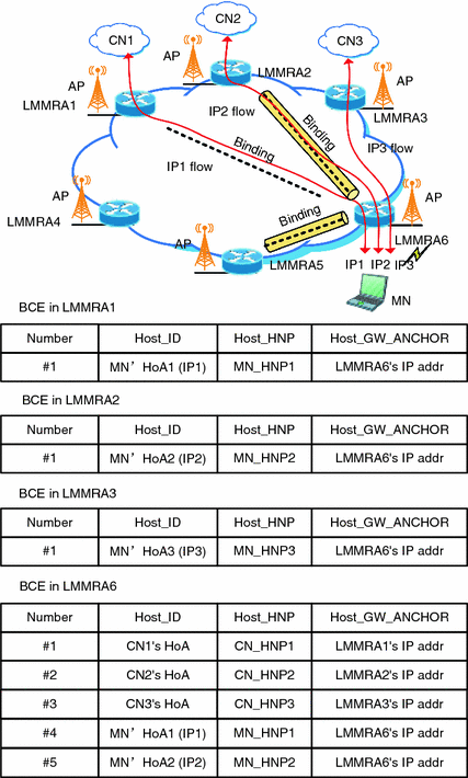
BCE in LMMRA6 while handover


3 Performance Analysis and Discussion
The impact of the velocity (v) and session arrival rate (λs) was presented in the signaling cost and the packet delivery cost between the previous DMM (PDMM) and the proposed RODMM (RODMM).
The impact of velocity on the signaling cost was investigated. It was found out that the velocity mainly affected the mobility rate that varies between 5 and 80 m/s.
Figure 9 shows the variation of signaling cost. As v is increased, the signaling cost (SCPDMM) is also increased for both kinds of DMM solutions, such as PDMM and RODMM. Particularly, RODMM mechanism consumed higher cost than PDMM mechanism. This is because RODMM solution requires the exchanging of route optimization signaling messages for every movement. Based on the results, it was confirmed that within RODMM mechanism, an MN having high velocity consumed high signaling cost to establish its optimized routing path.

Impact of velocity (v) on the signaling cost
The impact of session arrival rate on the packet delivery cost was also investigated. The λs was selected from 0.1 to 0.8, wherein the variation of packet delivery cost was observed.
As shown in Fig. 10, PCPDMM has rapidly increased with increasing λs since data packets are delivered on a nonoptimal routing path. In other words, the result indicated that the PDMM mechanism is higher than the RODMM since all packets consume bandwidth of not only the tunnel path cost but also the directly tunneled path. On the other hand, RODMM only consumes the bandwidth of the directly tunneled path from the CN’s mobility anchor.

Impact of session arrival rate (λs) on the packet delivery cost
The results presented in Figs. 9 and 10 indicated a trade-off for the RODMM scheme, wherein the signaling cost increases while the packet delivery cost reduces.
4 Conclusion
In this paper, we tried to develop a new PMIPv6-based route optimization mechanism in distributed mobility management network architecture that can solve some problems and limitations of centralized mobility management. By providing a novel mobility anchor, LMMRA, our proposed PMIPv6-based route optimization mechanism was adopted between MN and CNs. According to the new PBA and PBW message format and BCE, the tunnel will be created between the MN’s current anchoring point and the CN’s current anchoring point for forwarding all data traffic from and to MN. By using our proposed route optimization mechanism, as performance results, the signaling cost is increased, but the packet delivery cost will be decreased. And the predictive link layer mechanism will also minimize the handover latency and packet loss.
References
IMT-2020 5G Vision and Requirements. IMT-2020 (5G) Promotion Group, White Paper, pp. 1–20 (2014)
Perkins, C., et al.: Mobility Support in IPv6, IETF, RFC 6275, July 2011
Gundavelli, S., et al.: Proxy Mobile IPv6. IETF Network Working Group, RFC 5213, Aug 2008
Les, et al.: Evolved Packet System (EPS): The LTE and SAE Evolution of 3G UMTS. Wiley, Feb 2008
Ali, I., et al.: Network-based mobility management in the evolved 3GPP core network. Commun. Mag. IEEE 47(2) 58–66 (2009)
Liu, D., et al.: Distributed Mobility Management. IETF Network Working Group, draft-liu-distributed-mobility-02 (work in progress), July 2010
Chan, H. et al.: Problem statement for distributed and dynamic mobility management. IETF Network Working Group, draft-chan-distributed-mobility-ps-05 (work in progress) Oct 2011
CJ, et al.: A PMIPv6-based solution for distributed mobility management. IETF DMM Working Group, draft-bernardos-dmm-pmip-01 (work in progress), March 2012
Fabio, et al.: A Network-based Localized Mobility Solution for Distributed Mobility Management. In: 14th International Symposium on Wireless Personal Multimedia Communications (WPMC), Oct 2011
Ma, et al.: An AR-level solution support for Distributed Mobility Management. IETF DMM Working Group, draft-ma-dmm-armip-00 (work in progress), Feb 2012
Seite, P., et al.: Distributed Mobility Anchoring. IETF Network Working Group, draft-seite-dmm-dma-00 (work in progress), Feb 2012
Tsunehiko, et al.: X50–20070618-012-KDDI Call Flow for PMIPv6 Address Assignment. 3GPP2-TSG-X WG-5, June 2007
Author information
Authors and Affiliations
Corresponding author
Editor information
Editors and Affiliations
Rights and permissions
Copyright information
© 2016 Springer India
About this paper
Cite this paper
Wang, Y., Cheng, Y., Yu, L. (2016). A Study of Route Optimization Support in Distributed Mobility Management. In: Zeng, QA. (eds) Wireless Communications, Networking and Applications. Lecture Notes in Electrical Engineering, vol 348. Springer, New Delhi. https://doi.org/10.1007/978-81-322-2580-5_78
Download citation
DOI: https://doi.org/10.1007/978-81-322-2580-5_78
Published:
Publisher Name: Springer, New Delhi
Print ISBN: 978-81-322-2579-9
Online ISBN: 978-81-322-2580-5
eBook Packages: EngineeringEngineering (R0)