
Abstract
Spinal fixation devices are used in the lumbar and sacral spine primarily for stabilization, reduction of deformities and fractures, and replacement of vertebral elements affected by tumors or infections Slone (Radiographics 13:521–543, 1993). Spinal instrumentation of the lumbosacral spine is necessary for the treatment of many different conditions including herniated discs, spondylolisthesis, scoliosis, degenerative disc disease, spinal stenosis, tumors, and infection.
Access provided by Autonomous University of Puebla. Download chapter PDF
Keywords
- Pedicle Screw
- Degenerative Disc Disease
- Degenerative Spondylolisthesis
- Posterior Lumbar Interbody Fusion
- Transforaminal Lumbar Interbody Fusion
These keywords were added by machine and not by the authors. This process is experimental and the keywords may be updated as the learning algorithm improves.
The goals of lumbosacral instrumentation include:
-
1.
Stabilization
-
2.
Correction of deformity
-
3.
Reconstruction or replacement
-
4.
Facilitation and enhancement fusion
Internal fixation provides immediate stability; however, the devices are inadequate to withstand prolonged periods of stress and are likely to fail unless a fusion is performed at the time of the instrumentation [1]. Despite all the advances and new developments in spinal instrumentation, fixation failure and pseudoarthrosis continue to be a challenge to spine surgeons, especially at the lumbosacral junction [2].
Prior to the development of modern instrumentation techniques, the only way to maintain spinal alignment and stability after fusion for patients with deformity or fracture was with body casting (see Fig. 9.1). This method was the method of choice before the 1960s [2]. The large number of associated complications and inadequate fusion rates, reported as high as 50 %, led to the development of the Harrington instrumentation (see Fig. 9.2a, b), which quickly became the gold standard for the surgical treatment of scoliosis [2]. The Luque instrumentation system (see Fig. 9.3a, b) was introduced to address some of the shortcomings of the Harrington rod system [3, 4], specifically at the lumbosacral junction. This system consisted of sublaminar wires attached at multiple levels to ¼-in. rods, which was eventually modified to an L-shaped rod to prevent caudal and cephalad migration through the wires [2]. This system permitted for better coronal and sagittal balance [2–4].

Risser body casting for treatment of a child with early onset scoliosis

(a, b) Harrington rod spinal instrumentation with surgeon Paul Harrington pictured on the right. The breakthrough was the invention of the Harrington rod by Paul Harrington of Texas in the 1950s, whose stainless-steel rod with a ratchet and a hook at each end allowed the safe placement, on the back of the spine, of a metal strut, which could be lengthened to pull out a C-shaped curve to as near straight as possible

(a) Bilateral Luque rods for treatment of scoliosis. Note that the construct failed at the transition of T12 and L1. The Luque instrumentation is a segmental spinal instrumentation system, which uses sublaminar wires attached to the rod. (b) Intraoperative illustration of the segmental sublaminar wiring with bilateral rods
A decade later, two new techniques were developed, the Cotrel-Dubousset (see Fig. 9.4a, b) instrumentation and the Galveston technique. The Cotrel-Dubousset system allowed for three-column fixation using pedicle screws with numerous points of fixation proximally in combination with hooks [2, 5]. Later versions added sacral fixation for increased biomechanical strength. However, this system still lacked the ability to resist flexion forces at the lumbosacral junction, and pseudoarthrosis rates remained as high as 33 %, particularly for adult deformity correction [5]. The Galveston technique (see Fig. 9.5a, b), on the other hand, provided more stable and rigid fixation at the lumbosacral junction by introducing a contoured rod from the posterosuperior iliac spine into the ilium between the inner and outer tables. This increased stiffness in flexion and side bending, which significantly decreased instrumentation failures [2].

(a, b) The images are an example of Cotrel-Dubousset instrumentation. This new concept in spinal instrumentation was developed by Drs. Yves Cotrel and Jean Dubousset in France. It uses hooks and rods in a cross-linked pattern to realign the spine and redistribute the biomechanical stress (Images were borrowed from the internet)

(a) The Galveston technique for spinal fixation provides fixation at the lumbosacral junction by introducing a contoured rod into the ilium as shown here. (b) Images here demonstrate an AP and lateral radiograph of the Galveston rod spinal instrumentation in a patient with CP. This was used with Luque sublaminar wiring
Spinal instrumentation has come a long way from the initial hooks and rods used in the 1960s. Numerous techniques developed throughout the remainder of the twentieth century, including various modifications to the aforementioned rod constructs with hooks, wires, and screws. The development of pedicle screws in particular drastically changed spinal instrumentation and lumbosacral surgery. A variety of plates, sacral screws, iliac bolts, cages, and interbody devices continue to be developed. Simultaneously newer forms of instrumentation such as interspinous devices, dynamic stabilization devices, and arthroplasty are changing the face of spine surgery.
We will briefly introduce and review each of the types of instrumentation that are utilized in the lumbosacral spine and discuss the biomechanics, indications, advantages, and disadvantages of each.
1 Rods
Rods, either paired or unpaired, are commonly used for both posterior and anterior fixation. Anterior-based rod constructs will be discussed in further detail in the section on anterior instrumentation. Regardless of whether they are used anteriorly or posteriorly, they functionally span a segment of the spine allowing for fixation over multiple levels. They are used with either wires, hooks, screws, or a combination thereof to attach to the spine [6]. Historically, they were first used in 1964 by Knodt and were popularized by Harrington in the 1960s [6]. This method of instrumentation quickly became the gold standard for the surgical treatment of scoliosis over the following decade, as it provided superior stabilization to previous methods of body casting [2]. Classically, this method of instrumentation was non-segmental, implying only two sites of fixation, one proximally and one distally (see Fig. 9.2a). This is rarely used now due to the improved biomechanical strength and deformity correction with segmental correction and multiple points of fixation [1].
McAfee et al. in 1985 biomechanically analyzed three spinal instrumentation constructs in 25 cadaveric spinal segments. Conventional Harrington distraction instrumentation, segmentally wired Harrington distraction rods, and Luque segmental spinal instrumentation were compared in 61 biomechanical tests. Segmentally wired Harrington distraction instrumentation proved substantially advantageous at resisting axial loads in unstable burst fractures, while the Luque segmental spinal instrumentation with L-rods coupled together proved to be the best method of achieving rotational stability in translational injuries (fracture-dislocations) [3]. The biomechanical advantages of spinal instrumentation must always be weighed against the increased operative time, technical expertise required, and potential risks and complications of iatrogenic neurologic sequelae, neurovascular injury, and morbidity of surgery.
2 Hooks and Wires
Hooks (see Fig. 9.6) provide only posterior column support but remain an effective and versatile method for stabilizing the spine. Although they are more commonly used in the cervical spine, hooks remain a useful instrumentation tool for the lumbosacral spine as well. They may be anchored to the posterior elements via the lamina, pedicle, or transverse process (see Fig. 9.7). Laminar and pedicle hooks are used with rods to allow compression or distraction forces to be applied to the pedicles or laminae. They come in various sizes and shapes and engage the posterior elements by curving under (up-going hooks) or over (down-going hooks) the lamina (see Fig. 9.8) [6]. These hooks may have blunt or sharp ends or ridges to prevent slippage. The hook is held in place by lock washers, bolts, or set screws to the rod (see Fig. 9.9). Laminar hooks have been the workhorse of segmental hook fixation, but may not be used in combination with a laminectomy or for stabilization when there is injury to the lamina secondary to trauma and fracture. Pedicle hooks, however, provide a stronger anchoring point compared to laminar hooks but can only be placed up-going [1]. They are placed inferior to the pedicle at the facet joint. For example, the hook would be placed at the L1–2 facet joint for an L1 pedicle hook. Sacral hooks may be placed lower than pedicle screws in the sacrum and are often used as an adjunct to pedicle screws for an additional level of stability [6–8].

Illustration of a pedicle hook, lumbar lamina hook, and thoracic lamina hook

Anatomic illustration of the vertebrae and posterior elements including the pedicle and lamina as well as the pars interarticularis for review (©MMG 2002)

Radiograph demonstrating posterior spinal instrumentation with pedicle screws and laminar hooks. This lateral radiograph demonstrates the ability for laminar hooks to be placed either up-going or down-going

Image shows a pedicle hook with washer. Also note the sharp ends to help prevent slippage
Sublaminar wiring (see Fig. 9.10) involves passing a wire(s) around the lamina and rod or through a hole in the spinous process (interspinous wiring) [6]. The interlaminar space must be identified after removal of interspinous ligaments. The ligamentum flavum and soft tissue are released from the lamina, and the wire is passed caudad to cranial around the lamina [1]. Cables may be used instead of a wire, which are more pliable and less brittle (see Fig. 9.11) [6]. Sacral foraminal wires may also be used and are more secure than hooks, which have the potential to dislodge. Additionally, they are less bulky than hooks and are less likely to cause discomfort [6]. Nevertheless, these implants are placed dorsal to the mechanical axis of rotation at L5–S1, thus contributing to their high rates of failure [2, 7]. They rely on compressive and distractive forces for their purchase and have inferior torsional stability. Even though wire constructs have good sagittal stability, they have limited torsional stability and cannot provide compression or prevent longitudinal collapse [1].

Illustration demonstrates sublaminar wiring with rod along the posterior spine

Cable, both single and double loop, designed for sublaminar passage
Hook and wire constructs are most commonly used to correct deformity, namely, for scoliosis. Scoliosis remains their main indication for use; however, additional uses include treatment of trauma, tumor, degenerative spondylolisthesis and scoliosis, and disc disruption with fusion. Wires may be used without rods for the treatment of certain fractures. Sublaminar wires, hooks, and cables, particularly at the sacral level, lack the biomechanical strength to serve as rigid instrumentation. They have poor pullout strength compared to other constructs [9]. Lack of stability in flexion, rotation, and side bending led to “flat-back syndrome” and complications of sagittal plane imbalance [2]. Over the years, various advances led to the development of locking hooks, to help prevent the common failure mechanism of dislodgement. Up-going hooks and down-going hooks may be used at the same level, a claw mechanism, which helps to reduce dislodgment. Self-adjusting hooks for multilevel placement have increased the rigidity of hook rod constructs [1, 6].
Dislodgement is a significant disadvantage of the hook and rod systems, particularly before the development of claw mechanisms and locking hooks. Additionally, hook and wire slippage on the rod has been a commonly reported mechanism of failure in the literature as well as rod, hook, and wire breakage [10]. Another disadvantage of these constructs is that they are intra-canal space-occupying devices that have the potential to cause neural compression or injury. An advantage of hooks and wire systems is that they may be used for either compression or distraction to correct deformity. They have limited multi-planar stability [1]. They may be placed at multiple levels, providing segmental instrumentation, to help increase the rigidity of the construct and provide more precise deformity correction. Additionally, they are easier and quicker to insert than pedicle screws. They are easy to place and are a biomechanically favorable method of fixation over pedicle screws in osteoporotic bone because the anterior aspects of the laminae are the least affected by bone mineral density loss [1]. They are also the least expensive construct for posterior segmental spinal fixation.
3 Pedicle Screws
Pedicle screw fixation (see Fig. 9.12a–d) or transpedicle screws are a more recent advancement in spinal instrumentation and have become the workhorse for lumbosacral instrumentation. Pedicle screws are used most commonly in combination with fusion to enhance segmental stability. Other indications include deformity correction, degenerative conditions, fracture fixation, and treatment of tumors and infection. They provide superior biomechanical stability compared with other segmental constructs as they provide fixation in all three-columns of the vertebral bone. Functionally they provide excellent longitudinal (both compression and distraction), torsional, and sagittal stability [1]. They may be used with both plates and rods. Although they were first reported to be used in 1969 by Harrington and Tullos, they did not become popularized until several years later [6]. Various starting points (see Fig. 9.13) have been commonly reported in the literature, but the lateral border of the pars interarticularis and the middle of the transverse process is a great reference starting point. They are angled medially to pass through the pedicle and into the vertebral body. Depending on the vertebral level, both the angle and size of the screw will vary. Additionally, pedicle screws may be used in both open and percutaneous procedures (see Fig. 9.14a–d). They are attached posteriorly to rods or plates with clamps, or set screws. Pedicle screws are able to resist loads in all directions, and this three-dimensional rotational control makes them useful for correcting deformities, much more so than wires and hooks [6, 9, 11]. They provide three-column stability, being anchored to both anterior and posterior vertebral bodies, which is in contrast to the hook systems which are only anchored to the posterior elements [1]. The strength of fixation may be decreased when used in osteopenic bone or when they are inserted too shallow, which is a potential disadvantage in certain situations.


Images (a) and (b) demonstrate a polyaxial pedicle screw. (b) Postoperative lateral radiograph of two-level posterior lumbar pedicle screw instrumentation. Image (c) demonstrates various pedicle screw assemblies. (d) Axial CT image demonstrating bilateral pedicle screws entirely within the pedicle of the vertebrae without violation of the cortex

The illustrations demonstrate the proper starting point and trajectory for insertion of a lumbar pedicle screw

(a) Percutaneous wires for placement of lumbosacral pedicle screws. (b) Lateral fluoroscopic image of lumbosacral pedicle screws. (c) AP fluoroscopic image of lumbosacral pedicle screws. (d) Depicting the placement of percutaneous pedicle screw and rod instrumentation in the lumbar spine
Because of the three-column stability and the segmental fixation, pedicle screws can be used to deliver large corrective forces to the spinal column to treat scoliosis, kyphotic deformities, and other deformities [1, 12, 13]. They are ideal for fracture and dislocation stabilization after trauma. Pedicle screw fixation systems are most useful in correcting degenerative conditions for which the spinous processes and laminae are often removed for neural decompression [14]. Pedicle screw fixation allows stable attachment to a vertebra despite resection of the posterior elements and increases fusion rate when used in combination with bone grafting. Contrary to hooks and wires, they can be used to stabilize vertebrae after laminectomy [1, 15]. In addition, segmental control of the vertebrae is possible, allowing distraction and compression within the length of spinal fusion [14]. Overall, pedicle screws have superior biomechanical stability [1]. However, they are technically demanding to insert with significant potential risk for violation into the spinal canal and potential nerve injury. Additionally, they provide poor pullout strength in both osteopenic bone as well as the sacrum [1, 9].
Lumbosacral fusions may utilize pedicle screws; however, they are limited to S1 and S2. Sacrum pedicles contain less supportive cancellous bone. In order to improve biomechanical strength and pullout force, screws may be placed through two or even three cortices (sacral promontory) [6, 16]. However, long fusions ending at the sacrum with pedicle screws continue to pose problems for spine surgeons due to the forces on the lumbosacral junction. Failure rates have been reported to be as high as 44 % [2].
In a prospective randomized study, Zdeblick showed that the use of rigid pedicle screw instrumentation increased the chances of a successful fusion [14, 17]; however, the quality of the bone influences screw pullout strength and there is a considerable influence of various geometric variables of screw design on screw performance as well. Skinner et al. compared the relative performance of four different common pedicle screw designs on the market. Important principles from this study are:
-
1.
Improvements in pullout strength can be achieved by an increase in the outer diameter of the screw.
-
2.
Screw displacement before failure appears related to the screw pitch such that an increase in the pitch of the screw will increase the amount of displacement before failure.
-
3.
Screw angulation was found to have little effect on the pullout strength but may impact the screw displacement and energy absorption before failure [12].
4 Facet Screws
Translaminar facet joint screw fixation (see Fig. 9.15a–c) provides an alternative to pedicle screw fixation for spine fusion. Similar biomechanical performance has been shown between translaminar facet joint fixation with screws and pedicle screw fixation [14, 18]. The facet joint is the only true articulation in the lumbosacral spine. Thus, translaminar lumbar facet screws provide posterior stabilization of a single lumbar motion segment. They may be placed like pedicle screws either open or percutaneously. The screw is placed at the junction of the spinous process and contralateral lamina through the ipsilateral lamina across the articular surface of the facet joint [1]. This is most commonly used as supplemental fixation with ALIFs. The lamina must be left partially intact to perform this fixation; thus, decompression is usually a limited foraminotomy. Although this method of instrumentation is much less commonly used compared to other methods, it is the lowest profile construct that achieves stabilization when posterior bony elements are preserved [14, 19].


(a) Image demonstrates the proper technique for facet screw insertion. (b) Illustration demonstrates the trajectory of a translaminar screw. (c) AP and lateral radiograph demonstrating a one-level lumbar fusion utilizing a hybrid technique with two pedicle screws on the left at L4–L5 and a translaminar facet screw on the right at the L4–L5 facet joint
Historically, this method dates back to 1944 when Kin preformed Hibbs fusions along with supplementary facet screw fixation and reported a 91 % fusion rate in 44 cases. In 1984, Magerl described translaminar facet joint screw fixation, using a much longer screw through the entire lamina ending at the base of the transverse process [14]. This method is currently widely accepted and has been examined biomechanically and clinically with excellent results as an alternative to other spinal instrumentations [18, 20, 21]. There are few biomechanical performance comparison studies of translaminar facet joint screw fixation and pedicle screw fixation. Vanden Berghe et al. found that pedicle screw fixation and facet fixation perform similarly when tested biomechanically [14, 22].
5 Trans S1 Screw
Minimally invasive spine surgery continues to emerge. This growing trend continues to lead to advances for new surgical techniques as well as spinal devices to help decrease the morbidity and complications of spinal surgeons. Technologic advances have now allowed surgeons to perform L5–S1 fusions by posterolateral or anterior approaches through less invasive techniques. The AxiaLIF system (TransS1) (see Fig. 9.16a–c) allows the application of minimally invasive techniques to attain fusion at either L5–S1 or L4–S1 levels with a novel corridor of approach, described as the presacral “safe zone” [23] (see Fig. 9.16d). Anterior access to the L5–S1 disc space can be technically challenging and frequently requires assistance from a general surgeon for adequate exposure. Percutaneous paracoccygeal approach to the L5–S1 interspace is a minimally invasive corridor. Through this safe corridor, diskectomy and interbody fusion can be performed. It may provide an alternative route of access to the traditional open fusion procedures in patients with unfavorable anatomy [24] (see Fig. 9.16e).


(a) Demonstrates a sagittal CT scan of AxiaLIF instrumentation. (b) Demonstrates intraoperative AP and lateral fluoroscopic images of AxiaLIF interbody fusion in combination with percutaneous pedicle screw fixation. (c) Image depicts a schematic of an axiaLIF interbody fusion in combination with percutaneous pedicle screw fixation. (d) The illustration demonstrates access through the presacral fat for AxiaLIF interbody fusion. (e) The illustration depicts the procedural steps for an AxiaLIF interbody fusion
A transsacral rod may be applied through a paracoccygeal approach. Initially, this technique was utilized for single-level axial lumbar interbody fusion; however, recently it has been extended to perform a two-level fusion at both L4–L5 and L5–S1 levels. Indications vary but include back pain secondary to lumbar degenerative disc disease, degenerative lumbar scoliosis, and spondylolisthesis. Early clinical results and biomechanical stability are promising. Various studies have shown radiographic evidence of fusion to be 91 % [24]. The stand-alone rod reduced intact ROM significantly; however, supplementary fixation with facet screws or pedicle screws is required to achieve higher construct stability for successful fusion [25].
6 Interspinous Process Devices
Several interspinous spaces are currently available in the market. Though they vary in design and composition [26], their common mechanical goal is distraction between adjacent spinous processes, thus blocking intervertebral extension at that level. This theoretically provides an indirect decompression of the neural elements. Interspinous process decompression theoretically relieves narrowing of the spinal canal and neural foramen in extension and thus reduces the symptoms of neurogenic intermittent claudication. There are many proposed indications for their use including lumbar canal stenosis, grade I degenerative spondylolisthesis, discogenic low back pain, non-traumatic instability, lumbar disc herniations, and facet syndrome. However, there is limited evidence to support this wide use. The largest number of studies has been with the X-STOP device, a titanium alloy device that is placed between the spinous processes to reduce the canal and foraminal narrowing that occurs in extension [27] (see Fig. 9.17a–c).

(a) The titanium prosthetic X-STOP device. (b) Image demonstrates the placement of the prosthetic titanium X-STOP device between the spinous process. (c) Shown here is a postoperative lateral radiograph with a two-level interspinous process decompression with an X-STOP device
Biomechanical studies show that there is a beneficial effect on the kinematics of the degenerative spine. Other studies show satisfactory outcome to varying degrees. Anderson et al. compared the efficacy of interspinous process decompression with nonoperative treatment in patients with neurogenic intermittent claudication secondary to degenerative spondylolisthesis. The X-STOP device was more effective than nonoperative treatment in the management of neurogenic intermittent claudication secondary to degenerative lumbar spondylolisthesis [27].
7 Iliac Bolts
Recent advances and newer spinal instrumentation allow for insertion of screws into the ilium, independent of other points of fixation (see Fig. 9.18). Offset connectors are sometimes used to connect the iliac screws, or bolts, to the longitudinal rods. These screws are very long and provide fixation with pullout strength that has been shown to be three times higher than that of Galveston rods [2]. High fusion rates have been reported at the lumbosacral junction for both high-grade spondylolisthesis and long fusions [28].

Shown here is an AP radiograph with bilateral iliac bolts in combination with multiple level posterior fusion with pedicle screws and bilateral rods
Disadvantages include soft tissue dissection, which may potentially increase the risk of infection, reported to be 4 % over a 2-year period in one series of 81 patients [2]. Additionally, care must be taken to avoid violation of the greater sciatic notch and all the neurovascular structures there within; however, no injury to any of these structures has been reported in any major case series. The most common complications are instrumentation prominence and pain, which could require eventual removal. The main advantage is increased rigidity with increased fusion rates and decreased rates of pseudoarthrosis at the lumbosacral junction. Kuklo et al. reported a fusion rate of 95.1 % in 81 patients undergoing treatment for high-grade spondylolisthesis or long fusions to the sacrum with bilateral sacral screws, although 14 % of the patients reported discomfort over the iliac screw [29]. The main purpose of adding iliac screws is to decrease the risk of loosening and failure of the S1 screws, where there can be high stresses in longer constructs. They also offload the sacrum as a whole by transferring forces directly to the ilium.
Iliac bolt fixation was found to significantly decrease the flexion-extension moment on the ipsilateral S1 screw by 70 % and the contralateral screw by 26 % in a biomechanical study done by Alagre et al. in 2001 comparing fixation across the lumbosacral junction. Four different L2-sacrum constructs were evaluated with the following findings: (1) There is a significant decrease in the flexion-extension moment on the S1 screw when extending long posterior constructs to either the ilium or S2 sacral screw. (2) There is no biomechanical advantage of the iliac bolt over the S2 screw in decreasing the moment on the S1 screw in flexion and extension. (3) Adding anterior support such as an ALIF to long posterior constructs significantly decreases the moment on the S1 screw. Adding distal posterior fixation to either the ilium or S2 decreases the moment on the S1 screws more than adding anterior support [30].
8 Interbody Devices
During the past decade, interbody cages have grown in popularity as a useful device to obtain fusion. They may be used alone but typically need supplemental fixation. A variety of surgical approaches allow removal of the diseased disc and degenerative osteophytes, followed by correction of deformity with a cage that is inserted between the vertebral bodies. Thus, distraction of the disc space permits safer, indirect decompression of the intraforaminal zone, which is a common area of stenosis. These devices also theoretically tension the lax spinal ligaments, thus again indirectly decompressing the neural elements [31, 32].
Various interbody device materials have been used, including femoral ring allograft, carbon fiber or polyetherketone structural grafts, titanium mesh, or threaded interbody cage constructs [31, 33] (see Fig. 9.19a–d).


(a) Illustration here demonstrates an anterior lumbar interbody fusion with femoral ring allograft. (b) After the disc material is removed, the surgeon inserts bone graft material into the disc space, such as autograft or INFUSE® Bone Graft contained in an LT-CAGE® Lumbar Tapered Fusion Device, shown here, to restore the normal anatomic condition of the spine. (c) Viewed here is a CT scan with an interbody cage of the lumbar spine. (d) The schematic shown here illustrates an expandable cage inserted between two vertebral bodies. Autogenous bone graft is contained within the metal cage
Titanium mesh cages (see Fig. 9.20a–e) are utilized between vertebral bodies for fusions. These mesh cages are porous to promote and facilitate peripheral bone and vascular in growth. Typically, the cage is filled with morcellized bone graft [32]. Delloye et al. evaluated non-perforated cortical bone graft compared with perforated cortical bone graft in sheep models for incorporation. Although there was no statistical difference between both groups for union and bone density, the cortical bone graft porosity and the amount of new bone within the cortical bone differed significantly. Thus, porosity significantly improved the amount of newly formed bone by the host. The channels increased the interface between the host and the allograft and allowed for wider endosteal callus, which resulted in enhanced incorporation [34].


(a) The picture shown here is an example of a metal mesh cage used for spinal fusions (©MMG 2002). (b) This illustration demonstrates the placement of a mesh cage for anterior interbody fusion. Note that bone graft material is placed within the cage. (c) Here is a clinical photograph of a metal cage with autogenous bone graft contained within the cage. (d) Shown here is an AP and lateral radiograph of an L2/3 fusion, which was performed using a titanium mesh cage with an autogenous iliac bone graft and Z plate. (e) The image shown here is yet another example of a commonly used mesh cage for lumbar spinal fusion. Note the porosity within the cage to promote peripheral bone growth and vascular invasion
This procedure may be approached from many anatomical locations. As the push toward minimally invasive spinal surgery continues to grow, many new approaches have been invented to help minimize morbidity and complications. These various procedures are named based on the approach but all have the same conceptual goal of removing as much of the disc as possible and placement of graft and a structural spacer in the disc space. This facilitates correction of deformity and helps to optimize lordosis.
-
1.
Anterior lumbar interbody fusion, ALIF (see Fig. 9.21a–d)
Fig. 9.21 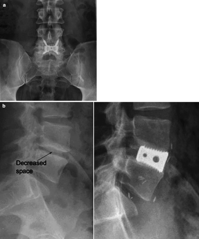

(a) This is a postoperative radiograph showing instrumentation for anterior lumbar interbody fusion with an intervertebral cage. (b) The image on the left is a lateral preoperative radiograph showing decreased disc space between L4 and L5 vertebrae. The image on the right is a postoperative radiograph of an interbody cage inserted with an ALIF procedure. The bone graft is contained within the metal cage and cannot be seen. (c) Viewed here is another example of an interbody fusion device that is inserted anteriorly with screw fixation into the superior and inferior vertebral bodies. (d) Shown here is a postoperative radiograph demonstrating a similar interbody fusion device to the one shown in (c)
-
2.
Posterior lumbar interbody fusion, PLIF (see Fig. 9.22a–d)
Fig. 9.22 
(a, b) Shown here are postoperative AP and lateral radiographs of a posterior lumbar interbody fusion. (c) This image depicts the placement of an interbody device between two lumbar vertebrae in a posterior lumbar interbody fusion procedure. (d) Two interbody cages may be placed posteriorly during a lumbar interbody fusion, side by side, to provide biomechanical stability for fusion as shown here in this schematic
-
3.
Transforaminal lumbar interbody fusion, TLIF (see Fig. 9.23a–c)
Fig. 9.23 
(a, b) Shown here are an AP and lateral radiograph of a transforaminal lumbar interbody fusion. Note the unilateral facetectomy on the right. (c) An example of an interbody cage that is used for transforaminal lumbar interbody fusion
-
4.
Direct lateral interbody fusion, DLIF (see Fig. 9.24a, b)
Fig. 9.24 
(a) The image shown here is an intraoperative fluoroscopy with blunt dilator over the target disc space. The preferred entry location is just anterior to the midline of the vertebral body. (b) This intraoperative lateral radiograph shows the placement of an interbody device. Anterior or posterior instrumentation may be added for improved stabilization if needed


Each of the different approaches offers its own advantages and disadvantages. Biomechanical studies indicate that anteriorly placed interbody devices significantly stabilize the motion segment in all directions except extension. Anterior fusion in primary disc lesions produces good results but may be of limited value for spinal stenosis, in which posterior procedures may allow for direct decompression [35]. Posteriorly placed devices provide less stability secondary to the required facetectomy for placement [36]; however, posterior lumbar interbody fusion and segmental pedicle-based plate fixation allow wide decompression and increased exposure for disc space preparation while maintaining stability with the screws. Placement of a PLIF cage does require a significant amount of neural retraction to gain access to the disc space (see Fig. 9.25). By moving the posterior trajectory more diagonally, the transforaminal approach preserves the interspinous ligaments as well as the contralateral laminar surfaces. Additionally, the transforaminal approach, which involves a full unilateral facetectomy, avoids significant retraction of the neural elements (see Fig. 9.26). Oftentimes, fusion surgery is approached from a “360° approach” with both anterior and posterior instrumentation to increase rigidity of the construct [31, 37]. Restoration of anterior column support prolongs instrumentation life, increasing fusion rates irrespective of the number of levels fused [38]. Most failures are the result of poor patient selection or technical difficulties with implantation [36].

Shown here is the dural retraction that is required during posterior lumbar interbody fusion

Shown here is a schematic of an open transforaminal interbody fusion and the associated unilateral facetectomy that is part of the procedure. The facetectomy allows placement of the interbody cage without significant retraction of the neural elements
Satisfactory outcome relies on a combination of discectomy, decompression, and deformity correction, in addition to achieving a solid fusion [38]. However, adding supplementary fixation reduces spinal motion and increases stiffness compared to stand-alone lumbar interbody fusion (see Fig. 9.27). Gerber et al. found that compared to stand-alone interbody cages, supplementary screw-plate fixation reduced the ROM by a mean of 41 % and supplementary pedicle screw-rod fixation reduced the ROM by a mean of 61 %. Anterior screw-plate fixation of L5–S1 ALIF had only a slightly larger ROM and slightly lower stiffness than L5–S1 ALIF with pedicle screws-rods [31].

Shown here is a postoperative radiograph of a corpectomy with interbody cage. Note that supplemental posterior instrumentation with pedicle screws and bilateral rod fixation
Interbody cages have shown to successfully promote fusion in a variety of animal studies and have shown acceptable clinical success rates [36]. Review of the literature concerning long-term results of decompressive procedures indicates short-term failure rates of 15–20 % and about 50 % failure rate by ten or more years after the index procedure. The surgical technique is demanding, fusion rates have been reported up to 96 %, and clinical success up to 86 % patient satisfaction [38].Comparison studies between posterior lumbar interbody fusion and transforaminal lumbar interbody fusion have shown similar operative times, blood loss, and duration of hospital stay in single-level fusions, but more complications were associated with the posterior approach [39].
Advantage | Disadvantage | |
|---|---|---|
ALIF | Allows for large interbody graft to be placed | May need access surgeon |
Can be used as stand-alone device | Must reposition patient if posterior procedure is needed | |
Risk of iliac vessel injury | ||
Risks to lumbosacral plexus leading to retrograde ejaculation | ||
PLIF | No need for access surgeon | Significant amount of dural retraction to place cage(s) |
No need to reposition patient | ||
TLIF | No need for access surgeon | Can lead to local kyphosis if interbody graft is not placed in anterior ½ of disc space |
No need to reposition patient | Relatively smaller graft compared to DLIF and ALIF | |
Less dural retraction than PLIF | ||
Facetectomy decompresses exiting and traversing nerve root | ||
DLIF | No need for access surgeon | Approach is trans-psoas, so can lead to hip flexion weakness |
Allows for large interbody graft to be placed |
9 Cages and Plates (for Anterior Fixation)
Anterior instrumentation has its roots in scoliosis surgery. In 1960, Dwyer placed anterior vertebral body screws which were connected by a tensioned wire. This wire was later replaced by a rod that could be locked rigidly to the screws to provide better rotational control and correction [1]. Cadaver biomechanical studies have shown that this system is one of the strongest constructs for anterior spine stabilization [1, 40]. Since the 1960s, the indications for anterior instrumentation have broadened to include fracture stabilization, and with this came the developments of plates. Plates were adapted for use on the spine from their original design for use on the extremities.
Plates (see Fig. 9.28a–c) today are most commonly used anteriorly in combination with cages for fusions in which the anterior plate places the graft material in compression. Plates can span multiple levels and maintain position and stability of the spine. They do not, however, provide a means to reduce or correct deformity the way pedicle screws do. Indications for use include kyphosis, flat-back syndrome, pseudoarthrosis, and failed posterior surgery. Care must be taken to avoid damaging adjacent soft tissue structures. Screws used in combination with plates should ideally be placed transcortically, which improves their holding power.

(a) Shown here is a schematic of an anterior plate. (b) Shown here is another example of an anterior plate that is used for instrumentation in the lumbar spine. (c) Viewed here is a four-hole anterior plate
Rods connected together can be used in a similar fashion anteriorly. If a single rod is used, the screw (see Fig. 9.29a–c) should be centered longitudinally and transversely within the vertebral body, optimally being parallel to the adjacent end plates in the coronal plane. If a double-rod system or plate is used, two screws should be placed in each vertebral body. Cross-linking with the double-rod Kaneda system enhances mechanical stability [1, 40].

(a) The image shown here is a radiograph of an interbody cage with supplemental anterior stabilization with bilateral rods and screw fixation. Note the trajectory of the screws within the vertebral bodies. There are additional cross bars interconnecting the two rods. (b) The image here depicts the Kaneda system that is used for anterior scoliosis correction. (c) Shown on this spine model is a single rod that is placed laterally along the vertebrae through an anterior approach
Advantages of anterior plate systems are that they are low profile. However, plates are less stable as a construct than anterior rod systems [40]. Single-rod systems are easy to apply especially when correcting multiple scoliosis levels but are relatively weak biomechanically. Double-rod systems provide superior biomechanical stability but are quite bulky. Any vertebral bone that was removed may be reused and packed into mesh cages. These devices are a weight-bearing device that provides structural anterior column support and increases the surface area of the bone graft that may hasten incorporation [1].
10 Lumbar Arthroplasty
Lumbar arthroplasties (see Fig. 9.30a–c) are designed to treat the early stages of degenerative disc disease, which is one of the most common spinal disorders in the population under 65 years of age [41, 42]. Despite the excellent short-term results of spinal fusion for traumatic and degenerative spinal disorders, several long-term studies have shown that alteration of the biomechanical environment leads to degenerative changes at adjacent mobile segments [43]. To avoid this problem, an artificial intervertebral disc replacement has been proposed as an alternative to spinal fusion.

(a) Here is an AP postoperative radiograph of a lumbar arthroplasty. (b, c) Here are two more lateral radiographs of two different arthroplasty devices with differing methods of fixation to the vertebrae
Bertagnoli et al. in 2002 prospectively evaluated 134 prosthetic discs using Prodisc II (see Fig. 9.31) in 108 patients for degenerative disc disease. They found that 90.8 % of patients had excellent results and no one had a poor result. Postoperatively, the average vertebral motion was increased in all patients at the operated level; however, degenerative at adjacent levels was noted in ten patients. Patients were able to resume their activities of daily living unaided at an average of 2.3 weeks. They encountered no implant failures or complications due to surgery [44].

The above image is a schematic depicting a lumbar arthroplasty. The two images below it are lateral flexion and extension radiographic images showing the preservation of motion
Nucleus arthroplasty is an emerging technology that could potentially fill part of the gap in treatment of degenerated discs. Prosthetic devices may be considered an additional therapeutic tool that can be used in selected cases of low back pain secondary to degenerative disc disease [38, 41, 45]. Many various types of arthroplasty devices have been developed to theoretically restore the normal kinematics and load-sharing properties of the natural intervertebral disc [45–47]. Optimal indications for use are disc height >5 mm and degenerative disc changes at an early stage (Pfirmann 2, 3), single-level disease, maintained integrity of posterior facet joints and lack of local anatomical contraindications, and failure of at least 6 months of conservative treatment [41]. Implant migration or dislocation has been one significant disadvantage of these devices [38]; however, few studies have focused on the ideal method of fixation between the prosthetic device and the vertebral body end plates.
NUBAC (see Fig. 9.32) is the first articulating nucleus disc prosthesis, designed to optimally respect the lumbar anatomy, kinematics, and biomechanics. It is constructed in a two-piece manufactured construct from polyetheretherketone (PEEK) with an inner ball/socket articulation. Balsano et al. reported on a 2-year follow-up study on 39 patients who underwent nucleus disc arthroplasty with the NUBAC device. Preliminary results are encouraging. There were no major intraoperative and postoperative complications. Both VAS and ODI scores at 2 years significantly decreased, which provide support that this may be a viable treatment option [41].

Shown here is an image of NUBAC, an articulating nucleus disc prosthesis used in the lumbar spine for optimal preservation/restoration of the normal anatomy, kinematics, and biomechanics
11 Dynamic Stabilization Devices
Recent developments have been made in posterior pedicle fixation to provide stabilization without fusing vertebral levels for the treatment of degenerative diseases of the lumbar spine. The goal of non-fusion stabilization is to reduce the mobility of the spine segment to less than that of the intact spine while retaining some residual motion. This may be beneficial since preservation of motion theoretically decreases the increased stresses at adjacent levels after fusion, thus potentially minimizing the accelerated rates of adjacent level disease. Pedicle-based posterior dynamic stabilization systems are relatively new; thus, long-term data are lacking in clinical studies, and short-term and midterm data are available for only some of these devices. There is a wide array of posterior dynamic stabilization systems available on the market, and indications for their use have varied substantially, ranging from degenerative disc disease to reconstruction after laminectomy for spinal stenosis. Conclusions cannot yet be drawn regarding the use of posterior dynamic devices compared to fusions [48].
Several in vitro studies have been conducted on a dynamic system that is currently available for use, Dynesys (see Fig. 9.33). Segmental ROM was reduced for flexion (less than 20 %), extension (approximately 40 %), and lateral bending (less than 40 %). In torsion, the total ROM was not significantly different from that of the intact level. There are theoretical biomechanical concerns about this device concept. The device is placed at a location posterior to the natural center of rotation of the intervertebral joint, which may preclude this dynamic compliant device from allowing substantial intersegmental motion [49]. Prospective case series have evaluated the radiologic changes in the intervertebral discs after dynamic stabilization. Disc degeneration at the bridged and adjacent segment continued despite dynamic stabilization [50]. Additionally screw loosening is not an uncommon problem. However, the early clinical outcomes of treatment with Dynesys are promising, with decreased pain and disability found at 1-year follow-up. Dynamic stabilization may be preferable to fusion for treatment of degenerative spondylolisthesis and stenosis by decreasing back and leg pain and avoiding the greater tissue destruction and morbidity associated with fusion [51]. However, larger, long-term clinical trials are required before definitive conclusions may be drawn.

AP and lateral radiograph demonstrating the Dynesys system for lumbar posterior spinal fixation
12 Conclusion
Spinal fixation devices are used in the lumbar and sacral spine primarily for stabilization, reduction of deformities and fractures, and replacement of vertebral elements affected by tumors or infections. Spinal instrumentation of the lumbosacral spine is necessary for the treatment of many different conditions. The goals of lumbosacral instrumentation include stabilization, deformity correction, reconstruction or replacement, and facilitation and enhancement of fusion.
Internal fixation provides immediate stability; however, the devices are inadequate to withstand prolonged periods of stress and are likely to fail unless a fusion is performed at the time of the instrumentation. Since the development of the first rod, hook, and wire constructs in the early 1960s, various developments and new devices have been invented to help minimize complications and hardware failure and enhance stability and fusion. However, there is a growing trend for instrumentation devices that preserve motion without fusion while avoiding stability, correcting deformity, and decompressing the neural elements. There are many devices utilized for lumbosacral instrumentation, each with their own benefits and drawbacks and indications for usage.
References
Bono CM, Garfin SR (2004) Spine, Orthopaedic surgery essentials. Lippincott Williams & Wilkins, Philadelphia, p 343, xiii
Kebaish KM (2010) Sacropelvic fixation: techniques and complications. Spine 35(25):2245–2251
McAfee PC, Werner FW, Glisson RR (1985) A biomechanical analysis of spinal instrumentation systems in thoracolumbar fractures. Comparison of traditional Harrington distraction instrumentation with segmental spinal instrumentation. Spine 10(3):204–217
Davies AG, McMaster MJ (1992) The effect of Luque-rod instrumentation on the sagittal contour of the lumbosacral spine in adolescent idiopathic scoliosis and the preservation of a physiologic lumbar lordosis. Spine 17(1):112–115
Lenke LG et al (1993) Ability of Cotrel-Dubousset instrumentation to preserve distal lumbar motion segments in adolescent idiopathic scoliosis. J Spinal Disord 6(4):339–350
Slone RM (1993) Spinal fixation. Part 2. Fixation techniques and hardware for the thoracic and lumbosacral spine. Radiographics 13(3):521–543
McCord DH et al (1992) Biomechanical analysis of lumbosacral fixation. Spine 17(8 Suppl):S235–S243
Stovall DO Jr et al (1997) Sacral fixation technique in lumbosacral fusion. Spine 22(1):32–37
Liljenqvist U et al (2001) Pullout strength of pedicle screws versus pedicle and laminar hooks in the thoracic spine. Acta Orthop Belg 67(2):157–163
Slone RM, MacMillan M, Montgomery WJ (1993) Spinal fixation. Part 3. Complications of spinal instrumentation. Radiographics 13(4):797–816
Liljenqvist U et al (2002) Comparative analysis of pedicle screw and hook instrumentation in posterior correction and fusion of idiopathic thoracic scoliosis. Eur Spine J 11(4):336–343
Skinner R et al (1990) Experimental pullout testing and comparison of variables in transpedicular screw fixation. A biomechanical study. Spine 15(3):195–201
Rose PS (2009) Pedicle screw instrumentation for adult idiopathic scoliosis: an improvement over hook/hybrid fixation. Spine 34(8):852–857; discussion 858
Deguchi M (1998) Biomechanical evaluation of translaminar facet joint fixation. A comparative study of poly-L-lactide pins, screws, and pedicle fixation. Spine 23(12):1307–1312; discussion 1313
Guyer DW, Wiltse LL, Peek RD (1988) The Wiltse pedicle screw fixation system. Orthopedics 11(10):1455–1460
Leong JC et al (1998) Comparison of the strengths of lumbosacral fixation achieved with techniques using one and two triangulated sacral screws. Spine 23(21):2289–2294
Zdeblick TA (1993) A prospective, randomized study of lumbar fusion. Preliminary results. Spine 18(8):983–991
Heggeness MH, Esses SI (1991) Translaminar facet joint screw fixation for lumbar and lumbosacral fusion. A clinical and biomechanical study. Spine 16(6 Suppl):S266–S269
Margulies JY, Seimon LP (2000) Clinical efficacy of lumbar and lumbosacral fusion using the Boucher facet screw fixation technique. Bull Hosp Jt Dis 59(1):33–39
Jacobs RR, Montesano PX, Jackson RP (1989) Enhancement of lumbar spine fusion by use of translaminar facet joint screws. Spine 14(1):12–15
Marchesi DG et al (1992) Translaminar facet joint screws to enhance segmental fusion of the lumbar spine. Eur Spine J 1(2):125–130
Vanden Berghe L (1993) Stability of the lumbar spine and method of instrumentation. Acta Orthop Belg 59(2):175–180
DeVine JG, Gloystein D, Singh N (2009) A novel alternative for removal of the AxiaLif (TranS1) in the setting of pseudarthrosis of L5–S1. Spine J 9(11):910–915
Aryan HE et al (2008) Percutaneous axial lumbar interbody fusion (AxiaLIF) of the L5–S1 segment: initial clinical and radiographic experience. Minim Invasive Neurosurg 51(4):225–230
Erkan S et al (2009) Biomechanical evaluation of a new AxiaLIF technique for two-level lumbar fusion. Eur Spine J 18(6):807–814
Bono CM, Vaccaro AR (2007) Interspinous process devices in the lumbar spine. J Spinal Disord Tech 20(3):255–261
Anderson PA, Tribus CB, Kitchel SH (2006) Treatment of neurogenic claudication by interspinous decompression: application of the X STOP device in patients with lumbar degenerative spondylolisthesis. J Neurosurg Spine 4(6):463–471
Harrop JS et al (2009) Iliac bolt fixation: an anatomic approach. J Spinal Disord Tech 22(8):541–544
Kuklo TR et al (2001) Minimum 2-year analysis of sacropelvic fixation and L5–S1 fusion using S1 and iliac screws. Spine 26(18):1976–1983
Alegre GM et al (2001) S1 screw bending moment with posterior spinal instrumentation across the lumbosacral junction after unilateral iliac crest harvest. Spine 26(18):1950–1955
Gerber M et al (2006) Biomechanical assessment of anterior lumbar interbody fusion with an anterior lumbosacral fixation screw-plate: comparison to stand-alone anterior lumbar interbody fusion and anterior lumbar interbody fusion with pedicle screws in an unstable human cadaver model. Spine 31(7):762–768
McAfee PC (1999) Interbody fusion cages in reconstructive operations on the spine. J Bone Joint Surg Am 81(6):859–880
Sasso RC, Kitchel SH, Dawson EG (2004) A prospective, randomized controlled clinical trial of anterior lumbar interbody fusion using a titanium cylindrical threaded fusion device. Spine 29(2):113–122; discussion 121–122
Delloye C et al (2002) Perforations of cortical bone allografts improve their incorporation. Clin Orthop Relat Res 396:240–247
Hutter CG (1985) Spinal stenosis and posterior lumbar interbody fusion. Clin Orthop Relat Res 193:103–114
Zdeblick TA, Phillips FM (2003) Interbody cage devices. Spine 28(15 Suppl):S2–S7
Lee SH et al (2006) Revision surgery of the lumbar spine: anterior lumbar interbody fusion followed by percutaneous pedicle screw fixation. J Neurosurg Spine 5(3):228–233
Enker P, Steffee AD (1994) Interbody fusion and instrumentation. Clin Orthop Relat Res 300:90–101
Humphreys SC et al (2001) Comparison of posterior and transforaminal approaches to lumbar interbody fusion. Spine 26(5):567–571
Hitchon PW et al (1999) Biomechanical studies on two anterior thoracolumbar implants in cadaveric spines. Spine 24(3):213–218
Balsano M (2011) Nucleus disc arthroplasty with the NUBAC device: 2-year clinical experience. Eur Spine J 20(Suppl 1):S36–S40
McAfee PC (2004) The indications for lumbar and cervical disc replacement. Spine J 4(6 Suppl):177S–181S
Lehmann TR et al (1987) Long-term follow-up of lower lumbar fusion patients. Spine 12(2):97–104
Bertagnoli R, Kumar S (2002) Indications for full prosthetic disc arthroplasty: a correlation of clinical outcome against a variety of indications. Eur Spine J 11(Suppl 2):S131–S136
McAfee P et al (2007) Treatment of lumbar spinal stenosis with a total posterior arthroplasty prosthesis: implant description, surgical technique, and a prospective report on 29 patients. Neurosurg Focus 22(1):E13
Cunningham BW et al (2003) Biomechanical evaluation of total disc replacement arthroplasty: an in vitro human cadaveric model. Spine 28(20):S110–S117
Kotani Y et al (2006) Multidirectional flexibility analysis of anterior and posterior lumbar artificial disc reconstruction: in vitro human cadaveric spine model. Eur Spine J 15(10):1511–1520
Bono CM, Kadaba M, Vaccaro AR (2009) Posterior pedicle fixation-based dynamic stabilization devices for the treatment of degenerative diseases of the lumbar spine. J Spinal Disord Tech 22(5):376–383
Gedet P et al (2009) Comparative biomechanical investigation of a modular dynamic lumbar stabilization system and the Dynesys system. Eur Spine J 18(10):1504–1511
Kumar A et al (2008) Disc changes in the bridged and adjacent segments after Dynesys dynamic stabilization system after two years. Spine 33(26):2909–2914
Welch WC et al (2007) Clinical outcomes of the Dynesys dynamic neutralization system: 1-year preliminary results. Neurosurg Focus 22(1):E8
Author information
Authors and Affiliations
Corresponding author
Editor information
Editors and Affiliations
Rights and permissions
Copyright information
© 2014 Springer-Verlag Berlin Heidelberg
About this chapter
Cite this chapter
Elston, J., Saldua, N. (2014). Lumbosacral Instrumentation. In: Patel, V., Patel, A., Harrop, J., Burger, E. (eds) Spine Surgery Basics. Springer, Berlin, Heidelberg. https://doi.org/10.1007/978-3-642-34126-7_9
Download citation
DOI: https://doi.org/10.1007/978-3-642-34126-7_9
Published:
Publisher Name: Springer, Berlin, Heidelberg
Print ISBN: 978-3-642-34125-0
Online ISBN: 978-3-642-34126-7
eBook Packages: MedicineMedicine (R0)