
Abstract
The explosion of March 2001 produced the collapse of the two statues, the instability all over the cliff, and a shear zone of hanging blocks in the back side of both niches. This part, despite of the destruction, is still very important because some plasters and excavated elements from the original outline are still on site. Because of this, the back side of the niches are sites to investigate in detail, to explore the connection between civil engineering, earth science, and restoration.
Access provided by Autonomous University of Puebla. Download chapter PDF
Keywords
These keywords were added by machine and not by the authors. This process is experimental and the keywords may be updated as the learning algorithm improves.
Introduction
The explosion of March 2001 produced the collapse of the two statues, the instability all over the cliff, and a shear zone of hanging blocks in the back side of both niches. This part, despite of the destruction, is still very important because some plasters and excavated elements from the original outline are still on site. Because of this, the back side of the niches are sites to investigate in detail, to explore the connection between civil engineering, earth science, and restoration.
Considering the positive experience developed in consolidating the Eastern Giant Buddha niche, it is reasonable to proceed, also in this area, with a similar plan of activity.
Following are some preliminary notes on the different parts of the back side of the niches, to be used as first input to the final design.
Endangered Vaults at the Base of the Niches
The removal of fragments from the ground of the niches, mainly in the Eastern Giant Buddha, has confirmed the large instability of blocks settled in the lower part of the back side, and the risk of collapse, in the vault. Additionally, in the Eastern Giant Buddha niche, a master crack was discovered just behind the fragments and parallel to the cliff, increasing the risk of fall also for a large portion of the back side. A numerical evaluation of the stability conditions of the cliff is not presently available, but the overall shear strength of rock mass is relatively low, in consideration of the wide opening (about 10 cm) of the fissure. Nevertheless, the persistence of this large crack was investigated in the nearby caves, likely showing a probable limited penetration into the lateral sides (Fig. 12.1).

The silhouette of statues on the back side of both niches (Western on left and Eastern on right). At the ground of Western Buddha are the remains of the March 2001 explosion. Note the height of the western niche (left) is about 55 m and the eastern niche (right) is about 41 m (From PASCO 2003b)
It is interesting to note that the crack probably represents the internal boundary of the statue’s rock excavation, because in the upper part of the niche a fracture is clearly delimiting the statue from the background massive material. Figure 12.2 shows the section of the Eastern Giant Buddha niche and the detected discontinuities either into the niche or in the close proximity cavities and temple, only in the western side. From this it is possible to verify the possible continuity of this crack along the entire section of the niche. The discontinuity belongs to the master system of fissures parallel to the front cliff, likely caused by the lateral detensioning of the most external part of the slope during the deepening of the Bamiyan valley. An additional important support could derive from the reconstruction of the rock sections destroyed by the explosion, to be decided together with restorers and archaeologists.

Reconstruction of upward and lateral propagation of the large crack, in red, discovered at the bottom of the vault, in the ground level, after the removal of the statue’s fragments (Topographic data from PASCO 2003a). The different thickness of the line stands for widening >10 cm (bold) and <10 cm (light). In green is the projection of lateral caves that were investigated to evaluate the propagation of the crack
In the vault the following problems still persist: collapse of small pieces of rock (minimum size ca. 30 × 30 × 30 cm), fall of large blocks of rock (around 1–2 m3), and possible instability of the entire back side because of the large discovered fissure. In such a condition it is strongly recommended to install temporary support by means of wooden pillars. They should be settled perpendicular to the vault, and stably fixed to the ground. When the pillars are not perpendicular to the ground surface, an appropriate small excavation to host it must be created.
The Back Wall of Both Niches
During the field work, a possible strategy for the consolidation of the back side of the niches was investigated. In such a way some preliminary ideas are presented here, to be further confirmed with some mathematical modelling and compared with the experience of restorers. This area is, in fact, a connection point between engineering geology specialists and experts of restoration. Nevertheless, according to some preliminary estimation based on a laser scanning map produced by PASCO (2003b) and photo interpretation, the surface still maintains the original feature in only about 7 % in the western niche (apart from an area of 10 % destroyed in 1707 that remained untouched from the recent explosion) and about 20 % in the eastern niche. The remaining part is now fresh rock, weakened by the explosion with the typical morphology and consistency of a “shear band.” In this area, any solution for securing the cliff has to be developed according to rock mechanics principles; at the contact between the original statue’s surface and fresh rock, the proposed solution has to fit with restoration principles, adapted to rock mechanics stability.
As a general principle, any possible strategy has to begin with the identification of the final requirement. In other words, whether the niche will be preserved as it is, there is the need for an accurate stabilization, avoiding block collapse and maintaining as much as possible its present state. If the final solution will consider, for example, the reconstruction of a new Buddha statue, a supporting structure to sustain some of the original fragments not totally destroyed yet is required. Such a construction must be adequately anchored to the intact rock mass and then the consolidation of the back side has to be designed having this in mind. The following notes have been elaborated considering, as a target, the need to maintain the present state of the niches, avoiding artificial reconstruction. In this light, the destroyed niches are the emblem of human incapacity to preserve properly its heritage, to take care of the traces of our passage on the earth.
According to the positive experience already conducted in the Eastern Giant Buddha niche, the general strategy for the back side conservation should include:
-
1.
Temporary support for the unstable blocks including the vault in the ground level. The existing net is certainly operating properly (Fig. 12.3), even if a better fixation at the underneath of the back side of the niche is required. This is to allow the safety of workers at the ground level. Presently the net is not completely fixed to the cliff and some falling rock may reach the ground. In the execution of a possible consolidation of the back side by means of scaffolding, the installation of more temporary steel cables, horizontally placed, is required.
Fig. 12.3 
The metallic net protecting from the detachment of small rocks from the shear band of destroyed statue. The photo also shows the wooden spacers, covered by nonwoven fabrics, placed on the niche to avoid any direct contact between the net and the remainder of the statue
-
2.
Damage assessment, in terms of surficial degradation and crack pattern distribution. The back side is heavily damaged, because the six contemporary dynamite explosions of March 2001 produced the total detachment of the rock, originating a typical “shear band” (e.g., a thickness of rock deformed by the laying down movement of a large portion of material). The real depth of the shear band into the rock mass is not very clear. Some estimation can be made from superficial inspection, but this can result in a large underestimation of the real situation. Figures 12.4, 12.5, 12.6, 12.7, 12.8, 12.9, and 12.10 provide an overview of the current status.
Fig. 12.4 
Detail of temporary net and of the shear zone on the back side of Eastern Giant Buddha niche
Fig. 12.5 
The shoulders of the Western Giant Buddha
Fig. 12.6 
(Top on the right) The shoulders of the Western Giant Buddha from the top
Fig. 12.7 
(Center on the left) Detail of detachment in the Western Giant Buddha
Fig. 12.8 
(Center on the right) The shoulders of the Eastern Giant Buddha
Fig. 12.9 
(Low on the left) The shoulders of Eastern Giant Buddha from the top
Fig. 12.10 
(Low to right) Detail of the detachment in the Eastern Giant Buddha
Damage assessment is an essential part of the work because any solution has to be designed in accordance with the volume of surface and detached blocks, persistence of cracks, and spacing of them into the rock mass. There are many methods to assess such damage assessment.
The best solution would require a direct inspection supported by geophysical prospecting, such as ground penetrating radar (GPR), to understand the exact distribution in the depth of detached material (Roch et al. 2006). Unfortunately, such a technique is not suitable in this case with the already installed metallic net. In fact, the electromagnetic waves emitted by GPR antennas are usually reflected by such metallic barriers, misleading the signal and then the resulting outcome. A surface inspection, from the scaffolding, may provide an accurate estimation at least in the external part of the surface. An estimation of density of cracks and persistence can be provided by means of traditional rock mechanics techniques such as the evaluation of block size and then the assessment of volumetric joint count (Jv; Palmstrom 1974, 1982, 2005). This approach has to be conducted directly on site, by means of proper scaffolding.
Nevertheless, in order to provide a preliminary estimation of the damage suffered from the back side of the niches from the explosions, the evaluation of the block size on the back side of the Western Giant Buddha has been conducted from laser scanning maps produced by PASCO (2003b) and available rectified photos. The aforementioned niche was chosen because an undeformed picture taken by climbers is available. Also an anaglyph image is available for this niche. An anaglyph mixes into one image a stereoscopic view using the complementarity of colors in the RGB channels. With coloured glasses, one can then filter the image and see the depth information of the model (Courtesy of Pierre Smars, ICOMOS).
Being an important parameter, the block size is represented, either explicitly or implicitly, in the main quantitative rock mass engineering classification systems used in the design of rock support, such as:
-
(a)
The ratio between RQD (Rock Quality Designation) and a factor for the number of joint sets (Jn) in the Q system
-
(b)
RQD and joint spacing (S) in the RMR system
-
(c)
Block volume (Vb) in the RMi (rock mass index), and the number of joints sets (nj) when RMi is applied in rock support evaluation
Also, the qualitative geological strength index system applies block size expressed as various degrees of blocky and broken rock masses in the determination of its values for rock mass strength (Palmstrom 2005).
The volumetric joint count (Jv) was introduced by Palmstrom in 1974. Earlier, a similar expression for joint density measurements was applied by Bergh-Christensen (1968) as the number of joints in a blast round. Being a three-dimensional measurement for the density of joints, Jv applies best where well-defined joint sets occur.
Jv is defined as the number of joints intersecting a volume of 1 m3. Where the jointing occurs mainly as joint sets
$$ \text{Jv}=1/S1+1/S2+1/S3+\dots 1/Sn$$where S1, S2 and S3 are the average spacings for the joint sets.
As has been shown by Palmstrom (1995, 1996, 2005), it is possible to correlate block volume (Vb) and the volumetric joint count (Jv). This is:
$$ \text{Vb}=\beta \times {\text{Jv}}^{-3}$$where β is the block shape factor, having the following characterization:
-
For equidimensional (cubical or compact) blocks β = 27
-
For slightly long (prismatic) and for slightly flat (tabular) blocks β = 28–32
-
For moderately long and for moderately flat blocks β = 33–59
-
For long and for flat blocks β = 60–200.
-
For very long and for very flat blocks β > 200
A common value for β = 36.
Palmstrom (1995) has shown that the block shape factor ( β ) may crudely be estimated from
$$ \beta \approx 20+7\frac{a3}{a1}$$where a1 and a3 are the shortest and longest dimensions of the block.
A chart for block estimation from Jv is reported in Palmstrom (1982).
The above concept has been applied to the Western Giant Buddha niche, for selected 2-D areas of 1 m2, were a rectified image is available. Given that the 3-D application is not possible to develop because the scaffolding is not yet installed, and the information on the propagation inside the rock of the effect of the explosion is not available, the result is only a first approximation. Figure 12.11 is a preliminary report of the distribution of the Jv for a detail of the Western Giant Buddha niche. In Fig. 12.12 all the niche is reported, showing the preliminary assessment of many areas of instability. Comparing these data with the chart of Fig. 12.13 in which the relationship between Jv and block size is reported, it is possible to estimate that 12 % of the surface exhibits block size smaller than 0.17 m3, 20 % exhibit block size between 0.17 and 0.6 m3, 43 % between 0.6 and 6.0 m3, and 25 % approximately less than 6.0 m3.
Fig. 12.11 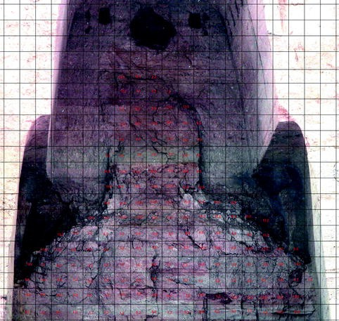
Distribution of the volumetric joint count (Jv) in a portion of the niche
Fig. 12.12 
Joint volumetric count for the Western Giant Buddha niche. Legend has been readapted from traditional classification (Palmstrom 2005) to fit the available data. In grey are original surfaces still preserved and in sky is the area resulting from the 1707 destruction
Fig. 12.13 -
3.
Establishing a proper consolidation strategy. Because it is not correct to define a unique solution all over the niche but there is the need to adapt different techniques at the different parts of the niche, as in previous works, it is absolutely necessary to perform a zoning of different problems (e.g., shallow detachments, cracks in the depth) in order to establish the most appropriate consolidation procedure. The damage assessment based on rock mechanics methodologies, possibly joined with some geophysical investigation, may allow the understanding of the thickness of the shear band to consolidate and the dimension of block size. In general, according to the preliminary damage assessment of Fig. 12.12, it is possible to say that such problems require the avoidance of collapse of portions of the rock face by recovering the original rock mass strength. The positive experience already conducted in the Eastern Giant Buddha niche suggests the use of similar techniques (e.g., passive anchors, nails, and grouting) but with different methodologies. Because this part of the niche still maintains the silhouette of the statue, it should be as little disturbed as possible. Likely, the removal of very few totally displaced small blocks would be required. Nevertheless, there is a need to tie together the single pieces of rock, originated by the laying down movement along the shear band. For small fragments, many types of nails can possibly be evaluated: pregrouted, stainless steel, carbon fiber, fiberglass. All these do not alter in time and provide a reliable strength. Mobilized shear strength has to be properly evaluated to assess density and distribution. This last is dependent on the grouting material that is another important element to consider; generally, it depends on the selected type of nail and the target (e.g., nailing an archaeological remain or very deep rock). In principle, the grouting material should provide the required bounding capacity to nail in order to: fit with the slaking problem of the rock, exhibit a similar (or slightly lower) mechanical strength and elasticity of original material, and not damage the archaeological remains. Considering also that the proposed solution requires a long time of execution and should possibly be implemented by a local firm, it is advisable to use a simple but efficacious solution. In this first hypothesis, three phases can be foreseen, likely with the use of stainless steel nails and passive anchors, making for a very simple procedure for installation:
-
(a)
The first phase has to be conducted in very blocky areas, with extremely low vibration and low water pressure cooling equipment (diamond head), for a depth of about 50 cm and a diameter less than 20 mm (nail 10 mm). This provides the opportunity to grout and nail the most superficial crust of the back side. In such a way a first resistant surface can be ensured. The grouting material to inject should be identified in coordination between restorers and consolidation experts, likely through field tests. A mortar already approved by Cultural Heritage Ministries could provide the most appropriate solution, avoiding chemical material in favor of a more natural product. In any case the low water release in the mixture, as a consequence of slaking for some siltstone strata, is a fundamental requisite. The proposed technique is similar to the one in use for the consolidation of masonry with microinjection. The spacing of such small grouting/injection can depend on the surface condition of materials and, as a first approximation, falls within the order of 50 cm.
-
(b)
The second phase is aimed at stabilizing the remaining shape of the figure till the master crack identified in 2006, in the underneath caves behind the feet of the Eastern Giant Buddha. In this phase it is expected to consolidate the material with grouting and nails, in order to obtain a homogeneous and stable rock mass, to a depth of no more than 3 m. In this case the drilling will be conducted with low vibration equipment, with diameters of about 32 mm (including the stainless steel nail of 16 mm and grouting). The spacing can here be considered relatively constant, on the order of about 1.5–2 m.
-
(c)
The third phase is aimed at fixing the consolidated mass to the stable rock of the cliff, and the grouting of the master crack identified in 2006. The stabilization will be conducted with passive anchors and grouting for a depth of about 10–15 m. The depth of anchors should be, in this case, twice the distance from the last detected large fissure encountered during the drilling. The diameters can be, as first sought, about 90 mm, in order to allow a correct placing of anchors. The spacing of such anchors will be evaluated through a stability analysis of the back side of the niche under present conditions. It is possible that anchors should be concentrated in the lower part of the niche, whereas in the upper part where the thickness of material is lower, the extension to 4–5 m. of passive anchors/nails foreseen in phase 2 can have satisfactory results.
-
(a)
-
(a)


Figure 12.14 shows the theoretical distribution of such nail/anchors in the Eastern Giant Buddha niche, and the relationship with the large crack detected at the inner back side (dashed red line). Real damage assessment is not considered in this sketch.

Tentative sketch for the stabilization of the back side of both niches (case study developed for the Eastern Giant Buddha). Pink, green, and blue stand for shallow nails, intermediate nails, and deep anchors, respectively; the dashed red line is the probable reconstruction of a large crack detected at the inner back side of the niche.
It is now clear that the proposed solution, with the three steps of drilling as previously described, is likely suitable to solve the target problem. The only uncertainty still to clarify includes the real nature of grouting material to inject for each of the three phases. Nevertheless, no final solution can be defined without a joint and fruitful cooperation within restorers and rock mechanics specialists. Even if the original part of the Buddha Statues is now a minor percentage with respect to fresh rock, there is no doubt that in this kind of work that is at the border among many disciplines, only a real collaboration can overcome misinterpretation and incorrect understanding of the real problems and needs (Plate 12.1).

The anaglyph image of the Western Giant Buddha niche. This technique is quite useful to display a static view of 3-D models. An anaglyph mixes into one image a stereoscopic view using the complementarity of colors in the RGB channels. With colored glasses, one can then filter the image and see the depth information of the model (Courtesy of Pierre Smars, ICOMOS)
References
Bergh-Christensen J (1968) On the blastability of rocks (in Norwegian). Lic Techn thesis, Geological Institute, Technical University of Norway, Trondheim. 320 p
Palmstrom A (1974) Characterization of jointing density and the quality of rock masses (in Norwegian). Internal report, A.B. Berdal, Norway, 26 p
Palmstrom A (1982) The volumetric joint count – a useful and simple measure of the degree rock mass jointing. In: Proceedings of the IV congress international association of engineering geology. vol 2. New Delhi
Palmstrom A (1995) RMi – a rock mass characterization system for rock engineering purposes. PhD thesis, University of Oslo, Department of Geology, 400 p
Palmstrom A (1996) The weighted joint density method leads to improved characterization of jointing. In: International conference on recent advances in tunnelling technology, New Delhi, 6 p
Palmstrom A (2005) Measurements of and correlations between block size and rock quality designation (RQD). Tunnels Underground Space Technol 20(2005):362–377
PASCO (2003a) Bamiyan mapping project. UNESCO report
PASCO (2003b) Buddhas laser scanner project. UNESCO report
Roch KH, Werner C, Bruckl E (2006) Potentials of monitoring rock fall hazards by GPR: considering as example the results of Salzburg. Landslide 3:87–94
Author information
Authors and Affiliations
Corresponding author
Editor information
Editors and Affiliations
Rights and permissions
Copyright information
© 2014 Springer-Verlag Berlin Heidelberg
About this chapter
Cite this chapter
Margottini, C. (2014). The Back Wall of the Niches: Preliminary Considerations. In: Margottini, C. (eds) After the Destruction of Giant Buddha Statues in Bamiyan (Afghanistan) in 2001. Natural Science in Archaeology. Springer, Berlin, Heidelberg. https://doi.org/10.1007/978-3-642-30051-6_12
Download citation
DOI: https://doi.org/10.1007/978-3-642-30051-6_12
Published:
Publisher Name: Springer, Berlin, Heidelberg
Print ISBN: 978-3-642-30050-9
Online ISBN: 978-3-642-30051-6
eBook Packages: Humanities, Social Sciences and LawSocial Sciences (R0)