
Abstract
Earls’ Oliva Palace was one of the referents of the early Renaissance and last Gothic in the ancient Kingdom of Valencia; victim of speculation and “elginism” practically disappeared during the first half of twentieth century. The dismantling operations carried out by Danish architect Egil Fischer, in order to reconstruct the most unique elements of the Palace in a new building in Denmark, included an extensive photographic report of the most relevant pieces as well as a rigorous graphic surveying, carried out, mainly by the architecture student Vilhelm Lauritzen. With this graphic documentation as a starting point, a 3D graphic restitution work of some of its pieces has been carried out with the aim of being able to visualize and understand these architectural elements of complex shapes. This 3D modelling has allowed manufacturing 3D scale models of the pieces that allow not only a visual perception, but also a tactile perception of the pieces, helping their comprehension and enjoyment by people with absence or difficulties of visual perception.
Access provided by CONRICYT-eBooks. Download conference paper PDF
Keywords
1 Introduction
The 3D printing has lately become a powerful tool, not only of display and spatial conception, but its potential goes beyond allowing the creation of prototypes in a quick and effective manner and even allowing the manufacture of items or unique elements at a reasonable cost. Its field of enlargement is quite wide from de artistic creation, the industrial designs, the engineering, the architecture, the archaeology and the biomedicine, only to mention some of the most relevant ones.
Another functioning of the models is to serve as a perceptive instrument so that people with visual impairment can have access to graphical and visual information. In the architectural heritage domain, there is a great deal of visual information, which is practically inaccessible for a blind person. The models used as a tactile perception tool allow these people with visual impairment to obtain information through the sense of touch.
Within the architectural heritage domain and the museology there are different approaches of study with reference to the development of devices directed to people with blindness or visual impairment. The tactile devices are used as didactic tools of support when visiting museums or spaces for cultural dissemination. We can establish the following types:
-
Embossed sheets, draws and tactile diagrams
-
Scale models and embossed plans
-
Models
In recent years, certain techniques have been developed for the rapid manufacturing of prototypes, in particular of additive manufacturing, commonly known as printing in 3D, which have made possible the realization of these models in a very effective manner [2].
In the field of architecture, several studies on the use of the architectural touch models produced through 3D printing have been carried out as the ones made by Voigt and Mr Martens. From the vast amount of digitized buildings belonging to the architectural heritage, it is possible to develop tactile models oriented to everyone and especially to people with visual disabilities. Through them, it facilitates the understanding of constructed architectural space [3,4,5,6].
At the national level, there are also remarkable experiences as the one carried out from the Universitat Jaume I, in collaboration with the Universitat Politècnica de València and Universitat Politècnica de Catalunya, with diverse positive experiences in the field of tactile drawings produced by printing 3D [7]. As well as other experiences that aim at the development of models and tactile plans enabling the dissemination of local architectural heritage among people with visual problems and the general public [8].
2 Earls’ Oliva Palace
Earls’ Oliva Palace was, in their times of splendour, one of the largest and most important Castle-palaces of the Kingdom of Valencia in the early 16th century. His great promoter was the earl Serafin of Centelles, noble humanist, who joined his palace Renaissance trends. These works, dated between 1511 and 1515, had to continue after the revolts of the Germanías (1520), being its main objective to strengthen the security of the Alcázar. His nephew, Francesc Gilabert, continued these works.
After the death of Pere de Centelles in 1569 and the incorporation of the County to the Duchy of Gandia, the Palace ceases to have a continuous use; so only minor maintenance works are held in it causing it to retain their original Renaissance style until its sale by the Osuna family in 1871.
From that moment the building began its decline, it was divided into parcels and the owners dispossessed it of all that which was feasible to dismantle. When the Danish architect Egil Fischer visited the Palace for the first time in 1917, despite its poor state, it awoke in him a great interest by the uniqueness of its decorative elements.
In 1918, Fischer bought several sections of the Palace and after presenting the Spanish Museum construction project to the Danish authorities and initiate the procedures for its construction, he began the work of cataloguing and disassembly in Oliva with the help of Vilhelm Lauritzen, making lots of scale plans of the most unique elements of the Palace, as well as sketches and photographs.
After a series of misfortunes and multiple complaints from the local authorities, the Palace was declared a national monument in 1920 and the exportation of its pieces was suspended. In 1932, due to some heavy rains, there was a collapse in a part of the Palace. Despite some attempts to retrieve it, the remains of the noble floor of the Palace were demolished in the 50 s disappearing with it all traces of this large building.
From the visit of Lauritzen to Oliva in 1976 on, it was established a link between him and the Mayor of Oliva at that time, Salvador Cardona, with the aim of recovering the few remains left of the palace in Denmark. In 1980 some parts of the Palace, including 2 metres of the frieze of the Hall of Weapons went on auction in London, were acquired by the Hispanic Society of America (HSA).
From this moment on it begins an intense research work on the Palace by Priscilla E. Muller, curator of the HSA. This research work was in connection to the town of Oliva, with Danish museums where it was deposited part of the material, with Vilhelm Lauritzen and Olga Fischer, who discovered in his house all plans made by her husband and by the young Lauritzen. This documentation was eventually donated by Olga Fischer to the HSA [9, 10].
Finally, after an agreement between HSA and the Town Council of Oliva, all this documentation returned to Oliva in 2010 becoming part of the cultural heritage of the town.
This documentation of great architectural and heritage interest is currently digitized and has served as the basis for the development of this work.
3 Objectives
The objective of this work is to achieve, through a complex process of graphic production, to obtain three-dimensional models that enable three-dimensional graphic restitution of some parts of the palace in order to be able to visualize and understand these architectural elements of complex forms. This three-dimensional modelling has made it possible to produce three-dimensional mock-ups of some pieces, which allow not only a visual perception of parts, but also a tactile perception of them by facilitating their understanding and enjoyment by people with absence or difficulty of visual perception. We will focus on a case study, which is the portal number 28 belonging to the Room 12, also known as Room of Lineages.
4 Background Documentation
The existing documentation from Portal 28 (Dör 28), located in Room 12, according to the Palace floor plan available is as follows:
-
Flat LA1144: It is a scale plan drawn to graphite on a sheet of paper of size 680 × 470 mm where is represented the elevation of the portal and a horizontal section by the jambs. Views correspond dihedral, the drawing on the slide layout is vertical and there are auxiliary lines of drawing. The plane does not have dimensions and its representation scale is 1:10 (see Fig. 1 left) [11].
Fig. 1. 
(Left) Plan Portal 28. LA1144. V. Lauritzen. (Middle) Cutting plane of Portal 28. LA1143. V. Lauritzen &/or E. Fischer.
-
Flat LA1143: It’s a sheet of transparent paper of size 680 × 490 mm; the disposition of the sheet is vertical. It is a copy of the elevation of Portal 28 drawn at flat LA1144. At this flat are numbered from 1 to 9 all the parts in which was divided Portal 28 for removing, starting at the left base and ending by the right base (see Fig. 1 right) [12].
-
Large Photo Album: On page 14R we find picture number 67 corresponding to Portal 28. Its dimensions are 7 × 10 cm. On the picture it is labelled the number of photography; it does not hold a very good quality, but a good condition of the portal can be perfectly observed (see Fig. 2) [13].
Fig. 2. 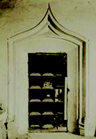
(Right) Pic. 64. Portal18. Photo Album Small. Page. 14R. E. Fischer.


5 Method of Graphic Restitution
From the starting documentation, the modelling on the portal in a CAD tool has been made, based on the orthogonal views of the parts by extrusion and revolution of the various elements and mouldings which form part of the piece individually: large prismatic bases, large moulded bases, prismatic bases of the small columns, moulded bases of the small columns, jambs and arches. Later subsequently, the different pieces have been placed in their position according to the original plan and they have been joined and intersected getting a common solid.
It is a complex process due to the large amount of elements which make up each of the pieces. The difficulty of the 3D modelling of this piece lies in the diversification of the guideline of the arc and in the modelling of the base as in the other pieces (Fig. 3).

D28 portal parts. Structured wired. Left: Large moulded base of small column. Right: semi-arch and left jamb.
Once the cover have been modelled, it was checked that the final geometry matched the background data and an orthogonal view of the portal, from a realistic point of view, has been performed, checking that the geometry as well as the joints between elements are correct and correspond with the original item (Fig. 4).

Portal 28: (Left) Picture. 64 AFG. Fischer. (Right) Elevation. 3D Graphic Restitution.
From this three-dimensional moulded the solids of the piece were created, making sure that the geometry is correct, being able to create a single solid and it has been exported to a LST file in order to make a three-dimensional impression of the pieces.
The Creation of the physical models has been carried out by different techniques of rapid prototyping of prototypes by the method of Additive Manufacturing, (AM), known as “3D printing”. During the process of manufacture or construction of its parts, the material is deposited slowly so that it progressively creates the geometry of the piece; they are also known, as in layers manufacturing techniques ([8], p. 187). Three printing techniques have been used: printing by deposition of plastic thread plastic (FDM), stereolithography (SLA), and printing powder (3DP).
The WANHAO Duplicator Printer i3Plus with a print speed of 50–250 mm and a thickness of 0.01 mm with strand of 1.75 mm in diameter has been used to print with wire. The maximum print size is 200 × 200 × 200 mm. The material used has been Green PLA plastic.
For resin printing it has been used a 3D printer XYZprinting Nobel 1.0a with Stereolithography (SLA) technology. The printable area maximum size is 128 × 128 × 200 mm and the material used has been transparent photosensitive acrylic resin. A thickness of 0.05 mm has been used.
Finally, the printer 3D Mod. Z 310 Printer has also been used. In this case the material is special powder printing zp® 150-caking zb® 60. The maximum print size is 280 × 220 × 200 mm and the thickness is of 0.1 mm.
6 Results
In the case of the models made with thread and photosensitive acrylic resin the results are acceptable, although the texture of the materials are not optimal for this type of architectural pieces, There also exist a great limitation on the print size The advantage of these materials is their toughness and resistance to bumps and drops (Fig. 5).

Model Portal D28. (Left) Printing with thread PLA. (Right) Printing with photosensitive resin.
Two printing tests of Portal D28 were conducted through the dust printer: one of the full cover, with a scale 1:20 and the other from the left base of the cover with a scale 1:7,5. In this case it is obtained a more architectural finish, with a texture similar to the original models (gypsum portals). The disadvantage of these models is its fragility. They can be treated with a consolidating, even though they lose their texture and original colour (Figs. 6 and 7).

Model of left base. Portal D28. Printing with printer Z printer 310. Material: zp® 150-caking zb® 60.

Model of portal D28. Printing with printer Z printer 310. Material: zp® 150-caking zb® 60.
7 Conclusion
The creation of physical models or mock-ups made by additive manufacturing techniques allow us to obtain physical models in a fast and effective way which enable us to be able to work in the field of inclusive design and heritage architecture, since there are numerous CAD digital information, which employed in a proper manner and, at the same time, simple and low-cost. They could serve as instrument for people with disabilities to access cultural content that otherwise would be inaccessible for them.
In the case study exposed in this article, one of the covers of the Condal Palace of Oliva is just one example of the numerous possibilities for inclusive and non-discriminatory actions based on the CAD information generated.
To complete the process it is necessary to count with the collaboration of affected users to check at first hand the effectiveness of the models and to be able to correct or improve certain aspects such as the scale, texture, and explanatory texts among others.
In this case study case the physical mock-ups acquire special importance as a tool for the dissemination of the architectural element for the general public, as these architectural elements do not currently longer exist physically and they are difficult to interpret for the general public from simple orthogonal views due to the geometric complexity of the piece.
The new technologies of digitization in construction through additive manufacturing (3D printing), allow us to currently represent a physical and tangible model to offer it as a resource for people with visual impairments, as well as for all those interested in the architectural heritage.
References
Consuegra B (1997) La visita al museo de alumnos ciegos y deficientes visuales. Integración Rev sobre discapac vis 24:47–50
Gual J, Serrano J, Máñez MJ (2015) Aplicación de la fabricación aditiva en la obtención de moldes para termoconformar gráficos tangibles orientados a personas con discapacidad visual. Tangible graphics using rapid prototyping techniques: volume as a design constituent. Span Digit J Blind Vis Impair 66:1–31
Gual J, Puyuelo M, Lloveras J (2014) Three-dimensional tactile symbols produced by 3D printing: improving the process of memorizing a tactile map key. Br J Vis Impair 32(3):263–278
Gual J, Puyuelo M, Lloveras J (2015) Improving tactile map usability through 3D printing techniques: an experiment with new tactile symbols. Cartogr J 52:51–57
Gual J, Puyuelo M, Lloveras J (2015) The effect of volumetric (3D) tactile symbols within inclusive tactile maps. Appl Ergon 48:1–10
Gual J, Puyuelo M, Lloveras J, Merino L (2012) Visual impairment and urban orientation: pilot study with tactile maps produced through 3D printing. Psychol: Ambiental-Bilingual J Environ Psychol 3(2):239–250
Voigt A, Martens B (2006) Development of 3D tactile models for the partially sighted to facilitate spatial orientation. In: Communicating Space(s): 24th eCAADe Conference Proceedings, University of Thessaly, Volos, Greece, pp 366–370
Máñez MJ, Gual J, Garfella JT, Martinez-Moya J (2016) Renaissance-Style Architecture en El Maestrazgo: from Virtual to Tactile Models. In: Amoruso G (ed) Handbook of Research on Visual Computing and Emerging Geometrical Design Tools. IGI Global, Hershey, Pensilvania, pp 174–200
Gavara J, Muller EP (2013) El Palacio Condal de Oliva. Catálogo de los planos de Egil Fischer y Vilhelm Lauritzen. Ajuntament de Oliva, Oliva, Valencia
Muller EP (1997) El Palau d’Oliva dels Centelles. In: Esteve A, Blai A (eds) El Palau dels Centelles d’Oliva. Recull gràfic y documental. L’associació cultural Centelles i Riu-sech, Oliva, pp 87–138
Lauritzen V, Fischer E (1919–1920) Planos. Museo Municipal de Oliva, Archivo Público Documental, Palacio Condal, Oliva, Valencia, p LA1144
Lauritzen V, Fischer E (1919–1920) Planos. Museo Municipal de Oliva, Archivo Público Documental, Palacio Condal, Oliva, Valencia, p LA1143
Fischer E (1917–1920) Álbum Fotos Grande. Museo Municipal de Oliva, Archivo Público Documental, Palacio Condal, Oliva, Valencia, p 14R
Author information
Authors and Affiliations
Corresponding author
Editor information
Editors and Affiliations
Rights and permissions
Copyright information
© 2018 Springer International Publishing AG
About this paper
Cite this paper
Martínez-Moya, J.A., Gual-Ortí, J., Jesús Máñez-Pitarch, M. (2018). Physical Scale Models as Diffusion Tools of Disappeared Heritage. In: Amoruso, G. (eds) Putting Tradition into Practice: Heritage, Place and Design. INTBAU 2017. Lecture Notes in Civil Engineering , vol 3. Springer, Cham. https://doi.org/10.1007/978-3-319-57937-5_69
Download citation
DOI: https://doi.org/10.1007/978-3-319-57937-5_69
Published:
Publisher Name: Springer, Cham
Print ISBN: 978-3-319-57936-8
Online ISBN: 978-3-319-57937-5
eBook Packages: EngineeringEngineering (R0)