
Abstract
Angiography is performed under sterile conditions with all necessary devices and equipment readily within reach of the angiographer. As most diagnostic and many interventional procedures are performed under conscious sedation, the room should be equipped with all required monitoring equipment and have necessary medications readily available. Assisting personnel should include nursing staff, preferably with critical care or emergency background, and radiology technicians familiar with the imaging equipment and techniques in use. The following is the example of the authors’ preferences.
Access provided by CONRICYT-eBooks. Download chapter PDF
Keywords
- Cerebral angiography
- Spinal angiography
- Equipment for angiography
- Sheaths
- Micropuncture set
- Arterial access
- Diagnostic catheters
- Guidewires
- Heparinized saline flush
Preparing the Angiography Equipment Table
-
The sterile angiography equipment table is positioned behind the operator who faces the angiography operating table (Fig. 1.1).
Fig. 1.1 
A sterile angiography table is usually positioned behind the surgeon for easy access to equipment. The setup shown is prior to the patient being prepped and draped. The tubing in the left lower corner of the figure will be used for heparinized flushes of sheath and catheters and will come to lie on the sterile drape of the operating table, rather than the angiography table. A guide wire in its sheath can be seen in the large blue bowl. Heparinized saline will be added to the bowl, and once the hydrophilic coating of the guidewire is activated, it is kept wet at all times. Same is the case for catheters. A micropuncture kit and access sheath lie next to the tubing on the surgical towel. A Guide catheter can be seen lying across the table. The red foam container for sharps with scalpel, syringe with local anesthesia, micropuncture needle, and 2-0 silk suture can be seen
-
The equipment table should be kept clean and uncluttered. The length of the table should be long enough that catheters and wires may be stretched out over it during preparation. If needed, two tables may be placed end to end for adequate space.
-
The table and the contents upon it are part of the operating field, and sterile precautions are maintained.
-
Sterile drapes for the patient and angiography operating table and sterile gowns and gloves for the operators may be opened on this table according to operator preference.
-
The table bears a round basin with sterile heparinized saline. The basin should be large and deep enough to hold wires and catheters when they are not in use. To ensure that the various catheters and wires don’t get entangled, each one is looped to fit the basin and may be wrapped at one point in a moist Telfa® or gauze piece. It is ensured that the heparinized saline in the bowl is clean and devoid of any clots or other foreign bodies. If a clot is detected, discard the saline for a clean supply.
-
A moist piece of Telfa or particle-free sponge should be available to wipe the wires when they are retracted from the catheter, and it should be replaced when any clot or debris is noted upon it.
-
A foam-bedded container for sharps is provided, and the micropuncture needle, scalpel, suture needle, etc., are stuck into it after use. Do not attempt to recap needles.
-
A manifold with a one-way valve may be used to dispense sterile heparinized saline, contrast, and waste fluids from syringes into a closed system. The manifold may be clipped to the equipment table or the angio table depending upon the preference of the surgeon.
-
Sterile cotton gauzes (4 × 4) and towels are also provided.

Instruments
-
The following basic equipment would be required for any procedure, diagnostic or interventional: micropuncture kit: 21G needle with 0.018 guidewire and 4 Fr dilator OR single wall needle: 18G.
Medications (with Typical Doses)
-
Fentanyl (e.g., 50–100 µgm IV) and Versed (0.5–1 mg) for sedation prior to arterial puncture. Administer additional doses through the procedure to maintain mild to moderate sedation, alleviating any anxiety while the patient is still able to follow instructions. These medications are not necessary if the procedure is done under general anesthesia.
-
Heparin is present in the flush systems (see below) and is also administered IV to maintain the desired ACT during interventional procedures. For flush systems, 6000 IU of heparin in 1000 ml of normal saline (6 IU/ml) is continuously administered at a rate of 30 ml/hr through each indwelling catheter or sheath used. During interventional procedures, a 5000 IU (or 70 IU/kg) of heparin bolus is usually administered after arterial access or once the Guide catheter has been secured in its position. In case of ruptured aneurysm, the heparin bolus may be deferred until the first coil has been placed. The ACT is measured 20 min after the bolus and then hourly. Additional heparin is administered as needed to maintain desired ACT. For goal ACTs, refer to specific procedure.
-
Consult a hematologist first, in case of heparin-induced thrombocytopenia.
-
2% Lidocaine for local anesthesia. Infiltrate skin with lidocaine prior to stab incision. Initially, raise a skin wheel and then advance the needle deeper into soft tissue. Before injecting, aspirate to ensure the needle tip is not in a vessel. Aspirate and inject as the needle is withdrawn.
Guidewires
-
We typically use 0.035″ or 0.038″ to support 5 Fr and larger catheters, e.g., Glidewire® (Terumo Interventional Systems, Somerset, NJ) for diagnostic catheters and Guide catheters.
Shape
-
Curved tip (30–60°) is useful for most selective catheterization.
-
Straight tips are useful when navigating the abdominal aorta to avoid renal or splanchnic vessel selection.
Coating
-
Hydrophilic coating, e.g., Glidewire®, may minimize friction and clot formation.
-
Coated wires should NOT be used with arterial access needles as the coating may be stripped if the wire is withdrawn through the needle, resulting in embolic complications. For certain procedures where a sheath is not inserted and repeated angiographies via the same artery are anticipated (e.g., intra-arterial chemotherapy for brain tumors), we use a Bentson wire (Cook Medical, Bloomington, IN). It can be inserted and slid back through the arteriotomy needle without sheering off any coating.
-
Table 1.1 shows common wires for diagnostic angiography. Refer to Chap. 5 for greater details.
Table 1.1 Common wires for diagnostic angiography
Sheaths
-
Placed to enable exchange of wires, catheters, etc., without losing arterial access or causing repeated trauma to the vessel (Fig. 1.2a, b). The sheath is connected to a continuously running flush of heparinized saline.
Fig. 1.2 
a Terumo Pinnacle sheath. Typically, 5 Fr is used for diagnostic purposes, while 6 Fr and larger are used for intervention. The sheaths are frequently color coded for size. In this picture, the dilator (tapered blue end extending beyond the white sheath tip) has been inserted into the sheath and is ready to be inserted over the wire into the vessel. The short tubing enables attachment of the sheath to continuous flush. The additional port on the side can be used to draw blood or for injections. The labeling at the back of the package enables rapid access to information for sheath election b. The size of the sheath (arrow) and its length (double arrows) and the size of compatible wires (curved arrows) are shown. The number in a rectangle (in the first row with double arrows) indicates the number of sheaths in the package. The expiry date (asterisk) can be seen. The package contents can be easily visualized from the front c. The color of the sheath and dilator cap readily indicates that it is 6 Fr. The packaging of a 5-Fr sheath can be discerned from the 6 Fr label shown above by the number as well as the different color (d, arrow). Similarly, the sheath itself and the dilator cap are also colored gray
-
5 Fr for diagnostic procedures; 6 Fr or larger for interventional procedures, e.g., coiling.
-
10–11 cm length is used for normal vasculature, 14 cm or longer for tortuous vasculature. May need to use an 80-cm or longer sheath, e.g., shuttle® sheath (Cook Medical, Bloomington, IN) in case intervention is required in tortuous vasculature.
-
2-0 silk suture or Tegaderm patch to secure the sheath, so that it is not displaced during procedure.
-
In children, a 4-Fr sheath should be used for diagnostic purposes.
-
Table 1.2 shows commonly used sheaths. The more commonly used specifications are indicated in bold. Refer to Chap. 5 for greater details.
Table 1.2 Commonly used sheaths are indicated below

Catheters
-
One typically selects one or two catheters as standard workhorses for diagnostic angiography. Familiarize yourself thoroughly with one or two diagnostic and guide catheters. Then, a few for situations like tortuous vasculature that is not amenable to navigation with the usual diagnostic or guide catheters. We typically use a 5-Fr glidecath® (Terumo Bloomington, IN) as our diagnostic catheter (Fig. 1.3a, b) and a 6-Fr or larger (depending upon the intervention) Envoy® guide catheter (Fig. 1.4a, b; Codman & Shurtleff Inc, Raynham, MA) for interventional procedures. If we anticipate that the diagnostic angiography will be immediately followed by intervention and the patient’s vasculature is not tortuous, we may use the Envoy guide catheter as the diagnostic catheter as well. This saves time and equipment, as switching from diagnostic to guide catheter is eliminated.
Fig. 1.3 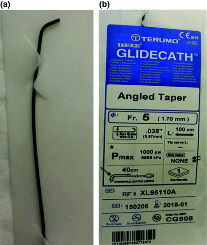
a Distal aspect of a 5-Fr angled glide catheter. The demonstrated angled tip shape is commonly used for angiography in normal vasculature. b Similar to the sheath, pertinent information is on a label and follows the same arrangement. The distal 40 cm of the catheter (arrow) is hydrophilic. The maximum pressure (P max) that this catheter can tolerate is 1000 psi (asterisk). Pressures greater than this will cause the catheter to burst. The label also indicates that the catheter has no side holes (double arrows)
Fig. 1.4 
Envoy guide catheter. A conduit for other devices to be readily advanced and retracted during endovascular interventions. It also provides stability, decreasing the likelihood of microcatheter collapsing during intervention. a The distal aspect of MPC (multi-purpose catheter) with the angled tip that aids in vessel selection. b The label demonstrates the size (6 Fr), inner diameter (0.070″ or 1.8 mm), length (90 cm), and the type of catheter (guide catheter). The expiry date is also readily seen (arrow)
-
In case of difficult vasculature, alternative catheters such as H-1 (Terumo) or Simmons 2 (Terumo) are used, instead of the usual diagnostic catheters (Fig. 1.5a, b). In the same vein, instead of an Envoy guide catheter, a shuttle sheath may be used, which is advanced to its intended position over an H1 slip catheter (Cook Medical) and 0.035 glidewire. The slip catheter and wire are removed once the shuttle sheath is suitably positioned. Refer to Chap. 5 for selection of appropriate catheters, sheaths, and wires.
Fig. 1.5 
Example of alternative diagnostic catheter. a Simmon’s 2 catheter. The tip is available in multiple modifications with larger of tighter loop. b The label demonstrates its name, size (5 Fr), caliber of compatible guidewire (up to 0.038″), length (100 cm), P max (1000 psi), curve tip type (Sim 2), etc. The arrangement of the label enables access to relevant information at a glance


Difference Between Sheaths and Catheters
-
The size of the sheath describes the internal (luminal) diameter, while in case of catheters it alludes to the outer diameter. Therefore, a 6-Fr sheath has a larger lumen than a 6-Fr catheter. Practically, this means that a catheter can be inserted into a sheath of same size, but not vice versa.
Setting up Flushes for Sheaths and Catheters
-
Heparinized saline in concentration of 6000 IU of heparin in 1000 ml of normal saline (6 IU/ml) is used for flush systems. The heparin is injected into the saline bag, maintaining sterile precautions. Run the heparinized saline through the tubing until it is completely free of any air bubbles. For neurointervention, no air bubbles or foreign bodies are acceptable in the tubing or catheters as they may result in embolic strokes.
-
To achieve a bubble-free system, priming is performed as follows:
-
Add 6000 IU heparin to a liter bag and ensure the bag is free of any residual air. Pre-prepared heparinized saline bags are also available.
-
Place the proximal tip of the tubing (the one closest to the drip chamber) into the provided inlet of the bag, maintaining sterile precautions.
-
Clamp the distal end of the tubing (this usually lies in the sterile field).
-
Pinch the line just distal to the chamber and squeeze the chamber. Then allow the inflow from the bag to fill one-third of the chamber.
-
Flick away any bubbles out of the chamber.
-
Do not completely fill the chamber with fluid, as monitoring of the flush rate will not be possible.
-
Now gradually release the hand pinching the line distal to the chamber. The fluid will advance from the chamber distally into the tubing.
-
Inflate the pressure system around the saline bag to 300 mmHg.
-
The distal clamp (on the sterile field) is released. The air in the tubing will advance out of the tubing, to be replaced by the air-free flush solution.
-
The flow rate of flush may be controlled using the distal clamp. We prefer using a pediatric transducer, which allows the fluid to flow at a uniform rate of 30 ml/hr. When needed, the rate of flow may be increased (e.g., when cleaning out the catheter or Touhy-Borst Y-Connector aka rotating hemostatic valve of blood) by releasing the regulator of the transducer. Depending upon the brand, this is done by action such as pressing the wings on either side of the transducer or pulling the ‘tail’ on the transducer (Fig. 1.6).
Fig. 1.6 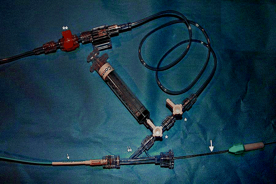
Proximal aspect of Envoy guide catheter (single arrow) attached by its hub (yellow) to a rotating hemostatic valve (RHV, double arrows). The guidewire (thick arrow) is introduced into the catheter through the RHV. The catheter is advanced over the guidewire into the patient’s vasculature. The wire is rotated back and forth as it is advanced, to prevent its tip from engaging and dissecting the vessel wall. This rotatory movement can be performed using the fingers holding the wire or a torque device (green and white) as shown attached to the wire, in a rubbing fashion against each other. It is ensured that the RHV cap is rotated clockwise to tighten around the traversing guidewire enough to prevent back bleeding, but still enable unobstructed movement of the wire. Two three-way stopcocks (asterisk) are attached to the side arm of the RHV, and the catheter is irrigated with continuous heparinized saline by tubing attached to the stopcock. The advantage of two stopcocks is that one can be used for manual injections while the other is used for connecting tubing from the autoinjector. The latter need not be disconnected since another port is available, and the preservation of a closed system prevents potential complications, e.g., introduction of air into the system. A neonatal transducer (double asterisks) is interposed between the tubing that enables continuous irrigation at 30 ml/hr. If a faster rate of irrigation is needed (e.g., to clean blood out of the catheter), the tabs/wings on either side are pressed together on this particular type of transducer
-
When a neonatal transducer is used, the distal clamp of the tubing is kept completely loose because the flow rate is controlled by the transducer.

Attaching Flush System to the Sheath
-
After a sheath has been placed in the artery, it will need to be connected to the flush system without introducing any air into the vasculature.
-
The sidearm of the sheath (intended for flush systems) usually has a built-in three-way stopcock. Turn it to allow backflow of blood into the sidearm tubing. Then make a wet connection with the flush system.
-
Turn the stopcock to also irrigate the side portal of the stopcock and purge any air. Then turn it again to open it to the sheath, with the blood being replaced by the clear heparinized saline.
-
To prevent unnecessary blood loss, close the three-way stop to the sheath during sheath insertion.
-
Connect the flush tubing to the sheath. There will be egress of saline through the open port of the stopcock. Press the wings (or alternative provided mechanism) of pediatric transducer to enhance the flow rate through the portal.
-
Then, the valve/stopcock is briefly closed to the flush system by turning it clockwise, resulting in backflow of blood (and any air) through the open sideport.
-
Then turn the stopcock to close it to the patient again and irrigate the side open portal clean.
-
Finally, close the stopcock to the sideport, establishing a continuous fluid column between the flush system and sheath.
-
We place a piece of gauze (4 × 4) at the sideport to soak up the exiting fluid and thereby maintaining a clean operating field.
-
An alternative technique is to connect the sheath to the flush tubing prior to insertion into a vessel. A continuous fluid column is ensured and then the dilator is advanced into the sheath, for insertion.
-
When the sheath has been introduced into the vessel and the dilator and guidewire removed, the stopcock is transiently closed to flush system, to allow backflow of blood.
-
Then the stopcock is turned anti-clockwise, so it is ‘closed’ to the patient. The neonatal transducer is used to quickly irrigate the vacant portal with heparinized saline.
-
The stopcock is turned to close the sideport and continuous fluid column established.
-
Be vigilant and ensure that the flush system continues to flow.
-
Any blood backing up into the tubing must be investigated. It may have occurred consequent to the pressure on the saline bag being inadequate (which should be 300 mmHg). Or, the system may be open to air at some point.
-
Do not allow blood stasis in the catheter or tubing as it can result in clot formation and emboli entering the patient’s vasculature.
Attaching Flush to the Catheter
-
This is usually performed while the catheter is still outside the patient.
-
Attach the flush tubing via three-way stopcock to the sidearm of the rotating hemostatic valve, which in turn is attached to the proximal portal on the catheter (Fig. 1.7).
Fig. 1.7 
Rotating hemostatic valves (a.k.a., Touhy-Borst Y-Connector or ‘Touhy’) with attached three-way stopcocks. For a diagnostic or guide catheter, we attach two stopcocks inline. This enables dedicating one stopcock outlet to the autoinjector, while the second can be used for manual injections or aspiration of blood. For microcatheters, a single three-way usually suffices, as we do not use autoinjectors with microcatheters
-
Allow heparinized saline to run through the tubing and catheter. For a short period, there may be an interruption in fluid emanating from distal the tip of the catheter, as the air is evicted (Fig. 1.8). Subsequently, continuous fluid flow will resume.
Fig. 1.8 
a Distal aspect of a front angled glidecath. The proximal aspect of the catheter is connected to a continuously running flush of heparinized saline, as shown in earlier figures. Prior to insertion into patient’s vasculature, ensure the catheter is air-free. Saline droplets should be noted to emanate continuously, without any interruption due to air bubbles. The hydrophilic catheter coating is activated by wiping it with moist Telfa and then not allowed to dry. b Once continuous column of heparinized saline running through the catheter is ensured, a moist guidewire is introduced into it, without allowing in any air bubbles. To achieve the same, the RHV is held upright when the distal softer end of the wire tip is introduced into it. The saline flush is accelerated by using the mechanism on neonatal transducer, to expel out any air that may have inadvertently entered during this process. The figure shows the distal tip of wire exiting out of the catheter tip (arrow). Prior to introduction of catheter into the sheath, the wire is completely retracted into the catheter. Once the catheter is within the patient’s vasculature, the wire is advanced such that it leads the catheter. A vessel is selected with the wire, and then the catheter advanced over it. When retracting the system, the wire should be entirely within the catheter
-
Ensure the entire system including the rotating hemostatic valve is free of air.
-
When introducing a wire into the catheter, hold the rotating hemostatic valve upright and then close it down just enough to ensure air does not enter the system. The RHV should be tight enough to prevent back bleeding or air entry, but still have some room so that the wire can be freely manipulated (Fig. 1.6).


Preparation of Patient
-
Position the patient supine on the neuroangiography table (Fig. 1.9a, b).
Fig. 1.9 
a A neuroangiography suite with the patient lying on the table prepped and draped. The autoinjector is prominent in the foreground, to the left. b Procedure underway. The Biplane angio with its prominent gantry at the head end of the patient is obvious. The monitor for visualizing fluoroscopic images is positioned such that the surgeon can view the images without any difficulty. Note the remote control within sterile pouch that the surgeon may use to perform tasks such as scrolling through images or angiography runs. The equipment table (not in view) is positioned behind the surgeon
-
A pillow or support under the knees may improve comfort for cases done under conscious sedation.
-
When the patient arrives in the suite, introduce the personnel and explain the procedure in simple terms (in elective cases, this should also have been done earlier). Explain what the patient might experience, e.g., a warm sensation on either side or back of face or neck when contrast is injected. Also warn about possible discomfort or pain when contrast is injected into branches of the external carotid artery. Explain the importance of remaining still when required and review the anticipated instructions such as holding of breath during angiography. During the procedure, periodically inform the patient about the progress and reassure that everything is going as anticipated.
-
Ensure good intravenous access with at least two large bore angiocaths.
-
Attach patient to monitors, such that heart rate, blood pressure, and respiratory rate are visible to the surgeon on the overhead monitor.
-
Ensure all pressure points are padded.
-
In case of interventions like carotid stenting where arrhythmias may be common, some operators prefer that the patient be attached to a pacemaker, so that in case of significant bradycardia pacemaking can be performed. Alternatively, atropine may be administered IV.
-
A headrest may be used, but sometimes may need to be eliminated if difficulties are encountered with the lateral view (B plane).
-
An adhesive tape may be placed across the patients’ head and around the table to encourage them to remain still. It should not be too tight to cause discomfort.
-
Shave both femoral regions and then prep using Chloroprep or Betadine. Maintain same sterile precautions as in the operating room.
-
The patient’s hands are kept at his/her side. If necessary, they may be gently restrained.
-
The patient is then draped with both femoral regions available for arteriotomy.
-
Administer anesthesia (local vs general) per operator’s preference and patient characteristics. We perform most procedures under local anesthesia with conscious sedation.
-
Conscious sedation is performed with 0.5–1 mg versed and 50–100 µgm fentanyl intravenously, prior to arterial access and periodically as needed throughout the procedure.
-
General anesthesia is induced by anesthetist.
-
Refrain from exclamations or remarks that may cause the patient anxiety or offense.
-
When performing arteriotomy closure at the end of procedure, forewarn the patient about possible transient discomfort. Administer additional dose of fentanyl and versed. Instruct the patient to take slow deep breaths, rather than holding breath and bearing down in response to pain.
-
Briefly review the results of procedure with the patient and whether further treatment is/is not anticipated. Advise the patient that you will be looking at the imaging in great detail later, and so the preliminary impressions may alter.

Suggested Readings
Osborne AG. Diagnostic cerebral angiography. Philadelphia: Lippincott Williams & Wilkins; 1999. p. 421–45.
Pearce M. Practical neuroangiography. Philadelphia: Lippincott Williams & Wilkins; 2007. p. 36–85.
Author information
Authors and Affiliations
Corresponding author
Rights and permissions
Copyright information
© 2017 Springer International Publishing AG
About this chapter
Cite this chapter
Khan, SN.H., Ringer, A.J. (2017). Preparing for Angiography. In: Handbook of Neuroendovascular Techniques. Springer, Cham. https://doi.org/10.1007/978-3-319-52936-3_1
Download citation
DOI: https://doi.org/10.1007/978-3-319-52936-3_1
Published:
Publisher Name: Springer, Cham
Print ISBN: 978-3-319-52934-9
Online ISBN: 978-3-319-52936-3
eBook Packages: MedicineMedicine (R0)