
Abstract
End-stage temporomandibular joint (TMJ) pathology resulting in anatomical architectural form distortion and physiological dysfunction dictates the need for total joint replacement (TJR). The complex nature of the TMJ’s functional relationship with the local anatomy and masticatory muscles and the technical requirements of implanting a replacement mean that it is unreasonable to expect the replaced joint to return to its premorbid, fully functional condition.
Access provided by Autonomous University of Puebla. Download chapter PDF
Keywords
These keywords were added by machine and not by the authors. This process is experimental and the keywords may be updated as the learning algorithm improves.
1 Introduction
End-stage temporomandibular joint (TMJ) pathology resulting in anatomical architectural form distortion and physiological dysfunction dictates the need for total joint replacement (TJR). The complex nature of the TMJ’s functional relationship with the local anatomy and masticatory muscles and the technical requirements of implanting a replacement mean that it is unreasonable to expect the replaced joint to return to its premorbid, fully functional condition.
The essential life functions of mastication, speech, airway support, and deglutition are supported by proper TMJ function and form. This puts the TMJ complex under more cyclical loading and unloading than any other body joint over a lifetime. Therefore, to provide long-term effective outcomes, the TMJ TJR device chosen must be capable of managing the anatomical, functional, and esthetic discrepancies that influenced its choice.
The surgeon should review the pertinent literature and use the TMJ TJR system that best meets the functional and form needs of each patient, based on reported long-term outcomes.
Based on the available refereed and edited literature, this chapter will present the well-accepted orthopedic criteria for the development and utilization of successful TJR devices to establish a rationale for the use of custom TMJ TJR device s in the long-term management of end-stage TMJ disorders.
2 Goals of TMJ Reconstruction
Regardless of whether the TMJ is reconstructed using an alloplast, allogenic, or autogenous materials, the following should be the management goals [1]:
-
1.
Improve mandibular function and form
-
2.
Reduce suffering and disability
-
3.
Contain excessive treatment and cost
-
4.
Prevent morbidity
Severe pathology with functional and anatomical distortion dictates the need for total joint reconstruction. Due to the complex nature of joint function and its related muscle function, it is not a reasonable expectation that a reconstructed joint can be returned to “normal” premorbid function. Therefore, there will always be some functional disability involved in any reconstructed joint. In the multiply operated, anatomically distorted joint reconstruction patient, chronic neuropathic pain will be a major component of that patient’s disability. Therefore, it is important for both the surgeon and the patient to understand that the primary goal of any type of TMJ reconstruction is the restoration of objective mandibular function and form. Any subjective pain relief gained can only be considered as of secondary benefit [2].
3 Indications for Total Alloplastic TMJ Replacement
Alloplastic total TMJ reconstruction salvage procedures should be considered for the management of end-stage TMJ pathologic conditions [3]:
3.1 Inflammatory Arthritis Involving the TMJ Not Responsive to Other Modalities of Treatment
Since inflammatory arthritis involves a local synovially mediated destructive systemic disease process, and complete synovectomy is not achievable, the orthopedic literature opts for an alloplastic joint replacement in these cases since the results are very predictable [4].
In the TMJ, alloplastic reconstruction has been discussed at length [1–11]. All of these authors agree that when the mandibular condyle is extensively damaged, degenerated, or lost, as in arthritic conditions, replacement with either autogenous graft or alloplastic implant is an acceptable approach to achieve optimal functional and symptomatic improvement.
However, dissatisfaction with some of the aspects of autogenous costochondral grafting, particularly in patients with high-inflammatory arthritic disease (e.g., rheumatoid arthritis) and ankylosis , led to the development and use of total alloplastic TMJ replacement (TMJ TJR) devices with data that can be evaluated to support good results.
Stern et al. [12] published a case report specifically dealing with the use of an alloplastic total TMJ system (Vitek II—Kent, Houston, TX). While this paper discussed using this modality to manage arthritic TMJ conditions, it was not until 1986, when Zide et al. [13] and Kent et al. [14] published their comprehensive review of rheumatoid arthritis and its surgical management that the subject was specifically addressed.
In 1994, Kent and Misiek provided a comprehensive review of partial and total temporomandibular joint reconstruction . They concluded that when there is a major vertical dimension problem, loss of disc and entire condylar head with chronic pain, hypomobility, malocclusion, such as in advanced arthritic conditions, total joint replacement with an alloplastic prosthesis, is indicated [7].
In 2000, Speculand et al. published a report of 86 total alloplastic joints (27 VK II (Houston, TX) and 59 TMJ, Inc. (Golden, CO)) used to reconstruct degenerative joint disease and rheumatoid arthritis with a median follow-up of 14.5 months (range 1–120 months). Using the subjective (pain and diet) and objective (interincisal opening) criteria they established for this study, they reported an overall success rate of 94 %. However, four patients required replacement of the VK II devices due to foreign body giant cell reaction s [15].
Saeed et al. in a 2001 publication reported on a series of seven patients with rheumatoid arthritis whose TMJs were replaced with TMJ, Inc. (Golden, CO) devices. After the mean follow-up of 30 months (range 8–50 months), they report improved subjective (pain and diet) and objective (interincisal opening) scores in these patients and concluded that patients with severe rheumatoid arthritis affecting the TMJ should consider alloplastic total TMJ reconstruction to restore some normal function and appearance [16].
Mishima et al. reported on 6 rheumatoid patients on whom they performed total alloplastic TMJ reconstruction s to improve respiratory status and correct occlusal discrepancies. They reported that after surgery, symptoms of daytime sleepiness and nighttime snoring improved, and each patient’s ability to masticate solid foods improved significantly. Postoperative cephalograms revealed that both posterior airway space and ramal height were significantly improved as did the dental occlusion. Mean oxygen saturation significantly improved 1 month post reconstruction, whereas apnea–hypopnea indices did not change significantly [17].
Wolford et al. in 1994 reported on the long-term results in 38 cases, followed for a mean of 45 months (range 10–84 months), with the use of autogenous sternoclavicular grafts in 3 groups of patients, one of which (n = 10) included patients with documented inflammatory arthritis. The results of this study showed that autogenous sternoclavicular joint TMJ reconstruction had excellent subjective and objective results when used to manage joints not affected by prior failed TMJ alloplastic devices (Proplast-Teflon or Silastic ) or joints affected by inflammatory arthritis. In the later, the procedure was successful by the subjective and objective criteria used for the study in only 50 % of the patients with inflammatory arthritis. Ankylosis requiring reoperation and replacement with an alloplastic total TMJ prosthesis was the typical sequelae in these failed inflammatory arthritis cases [18].
Freitas et al. reported on 12 arthritic nongrowing patients (24 joints) requiring total TMJ reconstruction . Six were managed with autogenous sternoclavicular or costochondral grafts and six with total alloplastic TMJ prostheses. Each group was followed for a mean of 48.8 months and 58.5 months, respectively. The authors reported that based on the criteria established for the study, the alloplastic TMJ replacement patients had statistically significant better subjective and objective results than did those reconstructed with autogenous bone. They concluded that in the light of these results and the fact that the alloplastic replacement avoided the need for another operative site and potential morbidity decreased operating room time and allowed for simultaneous mandibular advancement with predictable long-term results and stability that alloplastic TMJ replacement was more appropriate for total TMJ reconstruction in patients with low-inflammatory or high-inflammatory arthritic conditions [19]. They also reported long-term stability of the orthognathic component of management of these cases [20, 21].
In the late stages of the other inflammatory arthritic diseases such as psoriatic arthritis, juvenile idiopathic arthritis, systemic lupus erythematosus, Reiter’s Syndrome, gout, and pseudo-gout, or when severe condyle, articular eminence and glenoid fossa osteolysis result in functional and/or occlusal-facial dysfunction or ankylosis , TMJ TJR is indicated [4].
In light of these published experience in both the orthopedic and oral and maxillofacial surgery, and the literature comparing autogenous versus alloplastic total TMJ replacement in arthritic conditions, it appears that TMJ TJR is appropriate for the management for advanced stage arthritic disease of the temporomandibular joint (Fig. 5.1).

(a) High inflammatory arthritis patient (RA) preoperative. (b) Postoperative custom TMJ TJR (c and e). Preoperative. (d and f). 16 years postoperative
3.2 Recurrent Fibrosis and/or Bony Ankylosis Not Responsive to Other Modalities of Treatment
The traditional management of complete bony TMJ ankylosis has been gap arthroplasty with autogenous tissue graft or alloplastic hemiarthroplasty reconstruction [2]. While the autogenous grafting techniques develop form, mandibular function is typically delayed. Since autogenous graft mobility during healing will compromise its incorporation into the host environment or compromise its blood supply, early mandibular mobilization often leads to graft/host interface failure [9]. Matsuura et al. reported a high incidence of failure and ankylosis of autogenous costochondral grafts in sheep after condylectomy if the jaws were only partially immobilized [22].
Saeed and Kent reported a high incidence of re-ankylosis in patients with ankylosis who underwent autogenous costochondral TMJ reconstruction and advised caution in using this technique in this group of patients [23].
For the patient with re-ankylosis , placing autogenous tissue such as bone into an area where reactive or heterotopic bone is forming intuitively makes no sense. Orthopedic surgeons will typically opt for total alloplastic joint replacement in similar situations with other joints [24].
In the light of the biological considerations and the orthopedic experience, total alloplastic reconstruction should be considered in the management of these cases involving the TMJ (Fig. 5.2).

(a and b) Bilateral TMJ ankylosis in adult patient preoperative. (c and d) 5 years postoperative bilateral custom TMJ TJR
3.2.1 TMJ Ankylosis in Growing Subjects
Classically, pathologic, developmental, and functional disorders affecting the TMJ in growing patients have been reconstructed with autogenous tissues . Autogenous costochondral grafts (CCG) are reported as the “gold standard” for these TMJ reconstruction s [25–30].
In growing patients, theoretically autogenous (e.g., CCG) allografts will “grow with the patient.” However, often this so-called “growth potential” has been reported to be unpredictable or to result in ankylosis . These complications can occur either as the result of the allograft and/or fixation failure or because of the uncooperative nature of the young patient with physical therapy after reconstruction [25, 26, 30–32].
Studies have even questioned the necessity for using a cartilaginous graft to restore and maintain mandibular growth [33, 34]. Long-term reports of mandibular growth in children whose TMJs were reconstructed with CCG show that excessive growth on the treated side occurred in 54 % of the 72 cases examined, and growth equal to that on the opposite side occurred in only 38 % of the cases [35–40].
Furthermore, Peltomäki et al. reported investigations of mandibular growth after CCG, supported previous experiments with regard to the inability of the graft to adapt to the growth velocity of the new environment [41–43].
On the basis of the problems that have been reported with CCG TMJ reconstruction in children, such as graft failure, unpredictable growth, ankylosis , and potential for donor-site morbidity, and the orthopedic experience and success reported with alloplastic TJR in improving the quality of life of growing patients with severe anatomic and functional joint disorders, it seems reasonable to consider examining the feasibility of alloplastic TMJ TJR for the following conditions in children:
-
1.
High inflammatory TMJ arthritis unresponsive to other modalities of treatment
-
2.
Recurrent fibrosis and/or bony ankylosis unresponsive to other modalities of treatment
-
3.
Failed tissue grafts (bone and soft tissue)
-
4.
Loss of vertical mandibular height and/or occlusal relationship because of bony resorption, trauma , developmental abnormalities, or pathologic lesions
To continue to reoperate in children with failed, overgrown, or ankylosed CCG, with either autogenous bony or soft tissue replacements (or both), using the same modalities that failed previously, when there may be a more appropriate solution available, seems myopic. These patients would be better off undergoing alloplastic TMJ TJR knowing that, depending on growth, revision and/or replacement surgery may likely be required in the future, rather than incurring continued CCG failures that will also very likely require further surgical intervention in the future [44] (Fig. 5.3).

13-year-old ICR patient (a, b, and e). Preoperative bilateral custom TMJ TJR. (c, d, and f). 5 years postoperative (Courtesy of Dr. Donald Kalant, Sr. Naperville, IL)
3.3 Failed Tissue Grafts (Bone and Soft Tissue)
Ioannides and Maltha [45] reported the use of autogenous auricular cartilage led to the use of this technique in autogenous disc replacement. However, Takatsuka et al. investigated histologically auricular cartilage after discectomy in the rabbit TMJ and found fibrous adhesion of the grafted auricular cartilage to the condyle and the presence of a fibrous layer containing fragmented cartilage on the articular surface. They concluded that auricular cartilage did not appear to be an ideal material for disc replacement [46]. Other investigators reported similar results [47, 48].
The biology of autogenous tissue grafting success requires that the host site have a rich vascular bed. Unfortunately, the scar tissue always encountered in the multiply operated patient does not provide an environment conducive to the predictable success of free and occasionally vascularized autogenous tissue grafts. Marx reports that capillaries can penetrate a maximum thickness of 180–220 μm of tissue, whereas, scar tissue surrounding previously operated bone averages 440 μm in thickness [1]. This may account for the clinical observation that free autogenous tissue grafts, such as cartilage, costochondral, and sternoclavicular grafts often fail in cases of multiply operated patients or those with extreme anatomical architectural discrepancies resulting from pathology (e.g., failed autogenous materials).
The CCG has been the most frequently recommended autogenous bone for the reconstruction of the TMJ due to its supposed ease of adaptation to the recipient site, its gross anatomical similarity to the mandibular condyle , reported low morbidity rate at the donor site, and its growth potential in juveniles [25–30].
Reitzik reported that in an analogous situation to autogenous costochondral grafting, cortex-to-cortex healing after vertical ramus osteotomy in monkeys requires 20 weeks and probably 25 weeks in humans [49]. Typically in patients reconstructed with CCGs, maxillomandibular fixation is maintained for only 4–6 weeks in order to return the mandible to function and prevent ankylosis . Despite screw /plate fixation, micromotion of these free grafts will invariably occur with the early mandibular function resulting in shear movements of the graft leading to poor vascularization, nonunion, and/or potential failure [50]. This fact along with the compromise in vascularity discussed above undoubtedly account for autogenous CCG failures seen in these cases. Therefore, in light of the fundamental biological issues discussed and reported, TMJ cases involving multiply operated, failed prior alloplastic material s , anatomically distorted, and severe intra-articular pathology should be replaced with a total alloplastic device to achieve the optimum outcomes.
These results may along with the vascularity appear to be two reasons for failure of autogenous grafts in multiply operated TMJ patients, or those with severe anatomical discrepancies and/or end-stage TMJ pathology. Also, the work of Henry and Wolford indicates that reconstruction with autogenous materials is much less predictable than total alloplastic TMJ reconstruction , especially in the later scenario [51] (Fig. 5.4).

(a and b) Bilateral traumatically induced TMJ ankylosis preoperative status post 2 re-ankylosis after bilateral costochondral grafts. (c and d). 5 years postoperative bilateral custom TMJ TJR (Courtesy of Dr. Michael Bowler, New Castle, NSW, Australia)
3.4 Failed Alloplastic Joint Reconstruction
Due to the osteolysis around failed alloplasts and the resultant anatomical discrepancies of the host bone architecture, it is difficult to adapt and fixate autogenous materials stably to the distorted anatomical remnants of either the fossa or ramus. Further, the foreign body giant cell reaction s associated with failed or failing materials or devices provide a poor environment for the introduction of an autogenous graft as discussed above. Henry and Wolford’s results confirm this as they reported that reconstruction with autogenous materials was much less predictable than alloplastic replacement in these cases [51].
Mercuri and Giobbe-Hurder discuss this issue at length in a report where they evaluated long-term outcomes with total alloplastic TMJ reconstruction in patients with prior exposure to failed Proplast-Teflon and/or silicone rubber . They found that while the TMJ TJR devices remained functional long-term (60.2 months mean), the patients exposed to failed materials had lower subjective improvement scores (pain, jaw function, diet consistency) when matched to a group of patients never exposed to a failed TMJ alloplast. Therefore, based on the available literature, it appears appropriate to reconstruct TMJ affected by prior failed alloplastic material with TMJ TJR device s rather than autogenous tissues [52].
Orthopedists and biomedical engineers have been studying the effect of failed and failing devices on the long-term outcomes of future implanted alloplastic devices. There is now a question, yet to be answered, as to whether failure of a prior implanted device results in a cell-mediated immune response that negatively affects the outcome with any future implanted alloplast. This topic is discussed in detail in Chap. 9 (Fig. 5.5).

(a) Bilateral failed stock metal-on-metal TMJ TJR device s . Note the loose fixation screws and bilateral fractured fossas. (b) Bilateral custom TMJ TJR 12 years postoperatively
3.5 Loss of Vertical Mandibular Height and/or Occlusal Relationship Due to Bony Resorption, Trauma, Developmental Abnormalities, or Pathologic Lesions
Loss of posterior mandibular vertical dimension due to developmental abnormalities, pathology, or traumatic injury all result in a discrepancy in the occlusion of the teeth. This is manifested as either an anterior (bilateral loss) or lateral (unilateral loss) open bite deformity. These situations can be managed by diagnosis of the etiology of the problem and correction at the site of the pathology. In the case of primary TMJ etiology, joint reconstruction rather than osteotomy should be considered. Once again, the reconstructive surgeon must take into consideration the nature of the pathology, the patient’s prior local surgical history, and the state of the host bone architecture before deciding on the type of TMJ reconstruction . Discussion of management of extensive and complex mandibular segmental defects is in Chap. 6 (Fig. 5.6).

(a) Left TMJ low-grade fibrosarcoma preoperatively (b–d). Postoperative left custom TMJ TJR
4 Relative Contraindications for Total Alloplastic TMJ Replacement
4.1 Age of the Patient
Since total alloplastic TMJ reconstruction prostheses have no potential for growth, the benefits of their use in growing patients over autogenous tissue must be considered carefully before using them in such cases. This issue is discussed at length above (5.3.2.1).
4.2 Mental Status of the Patient
Is the patient psychologically prepared to handle the permanent loss of a body part with the understanding that revision and/or replacement surgery in the future may be required? Does the patient have unrealistic expectations of complete relief of pain and normal jaw function after alloplastic TMJ reconstruction ? Is the patient willing and able to do the post-implantation physical therapy required to obtain maximum functional benefit from the procedure? Many of the multiply operated, functionless TMJ patients require pre-reconstruction psychological counseling in order for them to accept the limitations of further surgery, should they choose to proceed.
4.3 Uncontrolled Systemic Disease
As with any form of an alloplastic implant in these situations, once the disease process in under control and the risk/benefit ratio is determined for the individual patient, implantation can proceed. This is also a relative contraindication for autogenous or allogenic implantation as well.
4.4 Active Infection at the Implantation Site
As with any alloplastic material , introduction into an infected or contaminated area can result in failure of the device to stabilize, leading to its failure under function. This is due to the unpredictability of the initial fixation of the device to infection-compromised hard and/or soft tissue . While this is true of all alloplasts, it is of particular concern with implants that have a planned function under load, such as any TMJ implant would. This is discussed in more detail in Chap.
4.5 Documented Allergy to the Implant Component Materials
Documented allergy to commercially pure (CP) titanium, titanium alloy, cobalt–chrome–molybdenum alloy, and ultrahigh molecular weight polyethylene (UHMWPE) is rare. Although 12–15 % of the population can be sensitive to the nickel alloy in cobalt–chrome–molybdenum components, far fewer reports of such allergic reactions have been reported in the orthopedic literature in total alloplastic joint patients. Patients with documented allergy to the component metals of any device should not be exposed to that material in any new device. This is discussed in more detail in Chap 9.
5 Established Criteria for Successful Alloplastic TJR Devices
After years of use, orthopedic surgeons developed accepted criteria for successful TJR device utilization [1]. Applying these well-accepted criteria to TMJ TJR long-term successful utilization, a rationale can be established for the use of custom TMJ TJR device s .
5.1 The Components of Any TJR Device Must Be Stable In Situ at Implantation
All implanted alloplastic devices depend on the principle of fixation component biointegration (screws in the case of TMJ devices) for their stability and longevity. Biointegration implies the direct incorporation of the fixation components by bone without the preliminary phase of fibrous tissue ingrowth. The requirements for biointegration are essentially the same as for primary fracture healing; basically the transmission of forces from the implant to the bone and vice versa must occur without relative motion or without intermittent loading. To assure long-term success, the most important principle in TMJ TJR must include the primary stability of the components at implantation [53].
The need for custom components in orthopedic TJR is uncommon. The bony anatomy of the pelvis, femur, and tibia affords the use of modular stock components that can be stabilized initially with screws , press-fitting, or cementation. The bony anatomy of the mandibular ramus and the temporal glenoid fossa do not provide such options for TMJ TJR. Therefore, all TMJ TJR device s must utilize screw fixation for initial fixation and stabilization of both the fossa and ramus/condyle components.
Compounding the anatomical and stability issues is the fact that most patients presenting with indications for TMJ TJR have deformed local bony anatomy. This may be the result of numerous failed prior surgical interventions, failed materials, as well as systemic primary or secondary end-stage disease pathology. Attempting to make stock TMJ TJR components fit and remain stable in these situations confronts the surgeon with a difficult challenge.
At implantation, to make stock TMJ TJR components fit, it is often the case that precious host bone must be sacrificed to create stable component-to-host-bone contact. To achieve a fit in complex cases, the surgeon may have to consider bending a stock component or shimming it with autogenous bone, bone substitute, or alloplastic cement. These tactics can lead to component or shim material fatigue and/or overload fostering early failure under repeated cyclical functional loading (Fig. 5.7).

(a) Failed stock TMJ TJR fossa fixation screw due to osteolysis resulting from cracked thin layer of PMMA shim (b)
Of more concern is the potential for the development of micromotion of any altered or shimmed component. Micromotion interferes with screw fixation biointegration which is necessary for component stability. Micromotion leads to the formation of a fibrous connective tissue interface between the altered component and the host bone. This can result in early loosening of the screw fixation leading to component mobility and potential early catastrophic or certain later premature device failure (Fig. 5.8).

(a) Failed right stock ramus component due to loose fixation screws resulting in micromotion. Note the development of the thick fibrous connective tissue mantle between the device component and the host bone as the result of micromotion (b)
Custom TMJ TJR components are designed and manufactured to each patient’s specific anatomical condition on a stereolaser (SL) model developed from a protocol-computed tomography (CT) scan. Therefore, the fossa and ramus components can be designed and manufactured to conform to any unique or complex anatomical host bone situation.
At implantation, neither the custom TMJ TJR components nor the host bone requires alteration or shimming to achieve initial component screw fixation and stability. The screw fixation secures the components intimately to the host bone mitigating the potential for micromotion and maximizing the opportunity for fixation screw biointegration.
5.2 The Materials from Which TJR Devices Are Manufactured Must Be Biocompatible
In 1960, Sir John Charnley reported the use of a total alloplastic prosthetic hip replacement system. He developed a metal-backed polyethylene polymer acetabular cup which articulated with a stainless steel femoral head component that was cemented in place with polymethylmethacrylate [54].
Modifications of this device using titanium (Ti), titanium alloy (Ti–6Al–4V), cobalt–chromium–molybdenum (Co–Cr–Mo), and ultrahigh molecular weight polyethylene (UHMWPE) have led to these materials becoming the gold standard for low friction orthopedic TJR. Acceptance of this management option for end-stage joint disease has made the modern practice of orthopedic surgery impossible without the availability of TJR devices [55, 56].
Employing the most advantageous physical characteristics of biocompatible materials is an essential consideration in the design and manufacture of any TJR device. Wrought, unalloyed titanium was originally chosen for endosteal implants and bone plates because of the rapid reaction of elemental titanium with oxygen in the air to form a thin chemically inert titanium oxide layer. This layer provides a favorable surface for biointegration of implant components with bone. Titanium also has properties of strength, corrosion resistance, ductility, and machinability. The extensive literature demonstrating its biocompatibility and biointegration makes titanium the metal of choice for the manufacture of the major components of TJR devices to date [57].
Co–Cr–Mo with its relatively high carbon content contributes to its strength, polishability, and biocompatibility. Its excellent wear characteristics when articulated against an UHMWPE presently make it the standard for the bearing surface for most orthopedic TJR devices [57].
Cast Cr–Co, often employed in the manufacture of stock TMJ TJR devices, is physically inferior to any wrought alloy. Metallurgical flaws such as inclusions and porosity found in cast Cr–Co components have been associated with the fatigue failure of metal-on-metal prostheses. These flaws may also lead to the failure of Cr–Co TJR components resulting in noxious metallic debris (metalosis) found in adjacent tissues [58] (Fig. 5.9).

(a) Failed right TMJ stock thin cast Cr–Co fossa. (b) Failed right TMJ stock cast Cr–Co ramus component
UHMWPE is a linear unbranched polyethylene chain with a molecular weight of more than one million. Testing over four decades of use in orthopedic TJR has led to the conclusion that UHMWPE is considered to have excellent wear and fatigue resistance for a polymeric material [59]. To date, no cases of UHMWPE particulation-related osteolysis have been reported in the TMJ TJR literature [60–63] (Fig. 5.10).

(a) Right custom TMJ fossa component retrieved after 12 years. Note the “dimple” indicating cold flow. (b) Light and (c) Polarized microscopy demonstrating little particulation
TMJ TJR materials are discussed in detail in Chap. 2 and 10 , and their possible effect on Periarticular tissues is discussed in Chap. 10
5.3 TJR Devices Must Be Designed to Withstand the Loads Delivered over the Full Range of Function of the Joint to Be Replaced
An important advantage afforded by a custom TMJ TJR is that the components can be specifically designed to manage the loads posed in the face of unique anatomic situations. For example, the center of rotation of the condyle of a custom TMJ TJR can be moved vertically to accommodate closure of the open bite deformity; or the ramus component can be shaped to accommodate the amount of available mandibular host bone. This ability to vary the design to cope with the existing anatomy leads to a more predictable result in any complex clinical situation [53] (Fig. 5.11).

Examples of the inability of stock components to deal with the variations in ramus anatomy caused by pathology resulting in the need for revision and replacement with custom components
Custom TMJ TJR design from anatomically accurate SL models will maximize screw fixation position options for initial component stability. The positions of the screw holes can be designed to avoid the inferior alveolar canal, thereby eliminating potential injury to its contents during fixation (Fig. 5.12).

Custom TMJ TJR device on SL model with exact fixation screw lengths indicated
Proper bicortical screw length can be predetermined and prescribed. This eliminates time consuming and frustrating intraoperative screw hole “probing” to determine the appropriate fixation screw length. Knowing the proper screw length eliminates the potential for placing screws that are too long, which may be the cause of functional pain. In the case of the fossa component, if the sharp tips of the fixation screws penetrate beyond the medial cortex of the zygoma they can irritate the temporalis muscle. In the case of the mandibular component, too long screw tip impingement on the medial pterygoid is the concern.
5.4 The Implantation Surgery Must Be Performed for the Proper Indications and Aseptically
As with any surgical technique, outcomes are only predictable when the procedure chosen is performed correctly and aseptically, for the proper diagnosis, at the appropriate time, for the right patient, and with the right equipment.
Schmalzried and Brown report that the major causes of orthopedic TJR failures are the result of failure of the surgeon’s implantation technique or the limitations of the device implanted to properly manage the posed anatomical situation. A custom TMJ TJR device mitigates both issues [64].
Ravi et al. reported the after primary total hip and knee replacements, the risks for dislocation and early revision in patients whose surgeons had carried out less than 35 procedures were 48 and 44 % higher, respectively, than in patients whose surgeons had carried out greater than 35 procedures [65].
In a prospective study to determine the risk factors related to total knee replacement surgical site infections, Levant et al. determined that of the factors studied, the time it took to complete the surgery was statistically significant [66]. Despite the fact that surgical site infection is low in TMJ TJR (See Chap. 8), it would appear that the surgical time it takes to make a stock TMJ TJR device fit is necessarily longer than placing a custom TMJ TJR device that is made to fit.
6 Relative Disadvantages of Custom TMJ Devices
6.1 Cost
Custom TMJ TJR is thought to be more costly than stock TJR or autogenous tissue for TMJ reconstruction , but the extra operating room time, personnel, and resources must be considered in the latter scenarios. Also, in view of the potential for increased autogenous tissue donor-site morbidity resulting in an increased length of hospital stay and the unpredictable nature of the results of autogenous tissue grafting, the economic impact of TMJ TJR is likely less overall. Since custom TMJ TJR components are designed “made to fit,” manipulation and implantation time will be reduced. In contrast, with stock TMJ TJR components, the surgeon must “make them fit” requiring increased time and incurring added expense.
6.2 Two-Stage Procedure Required for Ankylosis Cases
The protocol, CT scan generated, SL model from which custom TMJ TJR components are designed and manufactured has a reported mean dimensional accuracy of 97.9 % [67]. Therefore, in the case of ankylosis /re-ankylosis a two-staged protocol is recommended.
In the first stage, the surgeon must perform an adequate gap arthroplasty (2–2.5 cm) and insert a spacer or “place holder” (carved to fit silicone rubber block, ocular prosthesis, etc.) to prevent the reformation of tissue and/or bone while the custom device is designed and manufactured. The patient must be placed into maxillomandibular fixation (MMF) to prevent movement of the spacer or change in bony architecture and/or occlusion. A postoperative protocol CT scan is then made and the SL model developed. The custom TMJ TJR components are designed and manufactured from that model to the specific anatomical circumstances of the specific case (Fig. 5.13).

(a) Carved-to-fit silicone rubber spacer. (b) Spacer in place. (c) Axial view of spacer in protocol CT scan
In the second stage, the spacer is removed and the custom TMJ TJR components are fixated. An autogenous abdominal fat graft is placed around the articulation to inhibit formation of heterotopic bone and re-ankylosis . The patient then begins active postoperative physical therapy.
Pearce et al. described the use of preoperatively created templates to obviate the two-stage protocol described above [68]. Virtual Surgical Planning (VSP) can supply templates to assist in doing this in one-stage as well. However, many surgeons believe in order to realize all of the benefits afforded by a custom TMJ TJR device ; the best fit for the components will be achieved and assured by using the two-stage protocol. The concern often raised about maintaining MMF between stages is moot since ankylosis patients cannot open their mouths before the first-stage procedure.
6.3 Material Wear, Design, and Long-Term Stability
TMJ TJR is a biomechanical rather than a biological solution to end-stage TMJ disease . Therefore, as with any implanted functioning biomechanical device, revision surgery may be necessary in the future to remove scar tissue from around the articulating components. Replacement of one or both TMJ TJR components over time due to material wear and/or failure is also a prospect.
It has been demonstrated that the use of appropriate biomaterials and design parameters can decrease material wear and increase the longevity of TJR devices [69]. Proper choice of biomaterials based on their characteristics is presented above. Design and material wear characteristics related to longevity must be considered. Stock TMJ TJR systems with multiple “make fit” choices, designed and manufactured from either thin cast Co–Cr fossa or all UHMWPE fossa components, utilizing cast Cr–Co ramus/condyle components, can pose multiple design and material issues.
Metal-on-metal design geometry can only be applied theoretically to a TJR hip where rotation is the major functional movement. For a metal-on-metal TJR hip to be successful, it requires tightly constrained radial clearances of less than 200 μm between the all metal acetabular cup and the all metal femoral head. If this conformity is not achieved at surgery due to host anatomical conditions or surgeon fit miscalculation, wear associated metal particulation will lead to metalosis, osteolysis , loosening, and micromotion resulting in device failure [64, 70].
In orthopedics, metal-on-metal devices would never be designed for a non-constrained joint. The TMJ, even after TJR, has functional movements that are unconstrained. Stresses and strains directly or eccentrically vectored against an incomplete or inadequate component-to-host-bone interface during TJR create wear . Unstable, thin, cast Co–Cr fossa cyclically loaded by the metal condylar head can lead to micromotion, galling, fretting corrosion , component screw loosening, and/or thin cast metal fossa component fatigue and fracture (Fig. 5.9a).
Cold flow is the property which allows UHMWPE under loading to develop alteration of shape rather than particulation [59] (Fig. 5.10a). In orthopedic TJR this property dictates that the stable component of a TJR articulation (i.e., the fossa) is held in position and stabilized by a stronger material (metal). Custom TMJ TJR fossa components are designed and manufactured to that material specification. Further, the metallic component of a custom fossa offers solid structure through which the zygomatic arch fixation screws pass.
Stock TMJ TJR device s with an UHMWPE flange screw fixation design have the potential to develop material cold flow around the screw holes or fracture should micromotion occur if the surgeon cannot or does not make the fossa component fit properly. Cold flow of the resultant screw fixation hole can lead to loosening of the stock fossa fixation screws and increased micromotion under repetitive loading resulting in device failure.
Hallab listed eight reasons why an unbacked all-UHMWPE fossa component is not favored in orthopedics, especially when placed against host bone: increased back-side wear (component-to-host bone) under function; poor surface for bone fixation (hydrophobic UHMWPE vs. hydrophilic bone); decreased bone remodeling on the surface of the UHMWPE; no macro-texturing to enhance short and long-term bone attachment strength; can lead to increased potential for biofilm infection (due to decreased cell attachment); increased chance of “cold flow” and UHMWPE fracture; less control over host bone side implant orientation due to greater likelihood of osteolysis on the host bone side over time; and a poor surface for cementing which will probably result in high wear and micromotion [53].
Stock fossa components are designed without a posterior stop to prevent the TMJ TJR device condyle from displacing posteriorly. Should the stock condyle not be perfectly aligned in the center of the stock fossa mediolaterally and/or anteropoteriorily, the condyle can displace posteriorly and impinge on the tympanic plate and/or the auditory canal. This can result in pain and mandibular dysfunction, malocclusion, and facial deformity. There is also the potential for infection should there be a pressure-related perforation associated with the auditory canal. This is of special concern when using a stock TMJ TJR in combination with orthognathic surgical procedures [71]. The custom TMJ TJR fossa has a posterior stop, alleviating this concern (Fig. 5.14).

(a) Right stock TMJ TJR device condylar head displaced into the auditory canal after bi-maxillary orthognathic surgery due to lack of posterior stop as demonstrated in frame (b). (c) Custom TMJ TJR fossa exhibiting posterior stop that will prevent posterior condylar head displacement
Since the components of a custom TMJ TJR interface so well with the host bone and the screw fixation is stable from implantation, mandibular function can begin immediately after implantation. This is essential in severe anatomical joint disease because masticatory muscle function has been compromised over time making physical rehabilitation difficult if delayed.
Salter in his work on continuous passive motion after orthopedic joint surgery demonstrated the importance of early active physical therapy to the long-term functional results of joint surgery [72].
7 TMJ Concepts Custom TMJ TJR Surgical Technique [73]
7.1 Preparation for Surgery
The avoidance of contamination of the surgical site during any alloplastic TMJ replacement surgery is important, therefore, it is essential that complete sterility be maintained at the implantation sites throughout the procedure. The following patient preparation should be considered:
-
(a)
The patients should be directed to thoroughly wash and rinse their hair the night before surgery with a mild shampoo and avoid the use of hair spray or styling gels the day of the surgery.
-
(b)
As with any presurgical antibiotic prophylaxis regimen, IV antibiotic (e.g., cefazolin 1 g, clindamycin 600 mg) is begun 1 h preoperatively and maintained on appropriate dosing schedule IV during the postoperative hospital course. This is followed on discharge by 1 week of oral antibiotic (e.g., cephradine 500 mg, clindamycin 300 mg) at the appropriate dosage.
-
(c)
Anti-inflammatory steroid therapy to minimize edema may be started pre-incision (8–10 mg IV dexamethasone) and continued postoperatively as with other reconstruction or orthognathic surgery .
-
(d)
Anesthesia—the naso-endotracheal tube can be sutured to the nasal septum (2–0 silk) and the anesthesia tubing and equipment are brought toward the patient’s feet. This allows for the draping that follows to decrease the potential for contamination as well as permitting easier head movement in bilateral cases. (Fig. 5.15)
Fig. 5.15 
Naso-endotracheal tube secured to nasal septum with 2–0 silk suture and brought inferiorly away from the surgical sites
-
(e)
After the patient is anesthetized and the airway secured, the eyes should be lubricated and protected to prevent corneal abrasion, etc. (Fig. 5.16).
Fig. 5.16 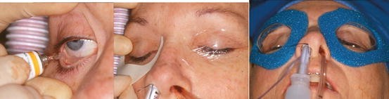
Lubrication of the eye. Taping the eyes shut. Application of plastic goggles to protect the eyes during surgery
-
(f)
Any hair that could become involved in the surgical field should be carefully arranged and/or parted to facilitate the skin incision. If the hair is to be sheared, care should be taken to avoid cutting or nicking of the skin in the area of the surgical incision.
-
(g)
After shearing the hair above the ear, pull the remaining hair away from the preauricular and surrounding areas and up toward the crown of the head.
-
(h)
Using foam tape, wrap the head circumferentially (forehead—above the ear—occiput) so that the hair is under the tape and off the skin over the preauricular incision site(s) (Fig. 5.17).
Fig. 5.17 
Using foam tape, wrap the head circumferentially (forehead—above the ear—occiput) so that the hair is under the tape and off the skin over the preauricular incision site. Note the sterile mineral oil-cotton occlusive dressing in the external auditory canal
-
(i)
The auditory canal(s) and tympanic membrane(s) should be inspected with an otoscope to ensure there is no preoperative infection and to document any presurgical pathology.
-
(j)
Occlude the external auditory canal on the surgical side. A cotton pledget moistened with sterile mineral oil is one option that can be utilized.
-
(k)
Intermaxillary fixation appliances (arch bars, Ivy loops, MMF screws etc.) should be applied prior to skin preparation and draping.
-
(l)
Retain all non-sterile fixation appliance application instruments on a separate Mayo stand to use later in the procedure when the patient is placed in the final occlusion for implantation of the device components. It is essential that there never be cross contamination between the mouth and the surgical wounds throughout the procedure.
-
(m)
After appropriate skin preparation in unilateral cases, a plastic adhesive isolation drape (e.g., 1010 Steri-drape [3-M, St. Paul, MN]) is placed from the contralateral submental area to the ipsilateral temporal area to isolate the mouth from the sterile surgical field. This type of draping allows for access to the oral cavity while maintaining sterility of the implantation sites during application of intermaxillary fixation later in the procedure.
-
(n)
In bilateral cases, first seal the mouth with a plastic adhesive occlusive dressing (Tegaderm, 3-M [St. Paul, MN] or Opsite [Smith and Nephew, London, UK]) (Fig. 5.18).
Fig. 5.18 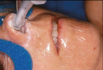
The mouth isolated with a plastic adhesive occlusive dressing (Tegaderm, 3-M [St. Paul, MN] or Opsite [Smith and Nephew, London, UK])
-
(o)
The nasotracheal tube and the nose can be further isolated using bilateral 1010 Steri-drapes as described above, then folding the loose ends together over the nasotracheal tube and nose in a sterile fashion and finally sealing them together with Steri-strips (3-M, St. Paul, MN).


7.2 Incisions
Standard preauricular and retromandibular incisions needed to access the TMJ area and the mandibular ramus respectively.
7.2.1 Preauricular (Modified Al-Kyatt [74]) Incision for Exposure of the TMJ Fossa
-
(a)
Find the crease between the helix and the preauricular skin and mark a line from the top of the helix to the lobe. In previously operated patients, use the scar to make this incision. In patients with multiple scars, excise the scarred tissue with the initial incision and revise the scar at closure. The superior aspect of the incision should be extended anteriorly and superiorly 4 cm at a 45° angle to the zygomatic process of the temporal bone.
-
(b)
Inject a vasoconstrictor (e.g., 1:200,000 epinephrine solution) along the line to be incised to decrease bleeding. Wait for its effect (3 min).
-
(c)
Apply traction to each end of the incision line with single-ended skin hooks.
-
(d)
With a #15 blade, incise the skin and subcutaneous tissue along the incision line.
-
(e)
At the superior aspect of the incision, spread the tissue with a curved mosquito hemostat to find the superficial layer of the temporalis fascia. This is the very obvious tough, shiny, white, and sinewy appearing dense tissue (Fig. 5.19).
Fig. 5.19 
Exposure of the superficial layer of the temporalis fascia
-
(f)
Once this layer has been found, slide the hemostat inferiorly along the top of this fascia to the area of the zygomatic arch.
-
(g)
Deepen the remainder of the incision to this plane using dissecting scissors remembering to stay close to the auricular cartilage posteriorly in the avascular plane. In the multiply operated patient, this is more difficult due to the scar tissue . Care must be taken to avoid cutting or nicking the auricular cartilage to avoid a postoperative chondritis.
-
(h)
Using blunt retractors, retract the skin flaps. Care must be taken to avoid penetration of the parotid capsule at the inferior aspect of the incision as this may lead to persistent bleeding.
-
(i)
At the tragus, in previously unoperated patients, just above the parotideomasseteric fascia, is the tragal ligament beneath which are found the auriculotemporal nerve and the transverse facial artery, both of which can be sacrificed.
-
(j)
Once the parotideomasseteric and superficial temporal fascias have been exposed, make an incision approximately 2 cm long at a 45° angle through the superficial layer of the temporalis fascia. The deep temporal vein crosses the zygomatic process of the temporal bone and can be cauterized at this point to avoid persistent bleeding. Extend this fascial incision across the posterior aspect of the temporal bone inferiorly along the posterior aspect of the condyloid process (Fig. 5.20).
Fig. 5.20 
45° angle incision through the superficial layer of the temporalis fascia
-
(k)
Reflect this fascial flap anteriorly along the zygomatic process of the temporal bone exposing the lateral aspect of the fossa and the articular tubercle (Fig. 5.21). Care must be taken not to tear this tissue as branches of the facial nerve course through it in this area. Electrocautery and retraction should also be done in a judicious manner to avoid injury to these nerves as well. In the multiply operated patient, this step is made more difficult due to scar tissue. This flap may have to be elevated with the assistance of dissecting scissors cutting the scar tissue away from the temporalis muscle above the zygomatic process of the temporal bone as the flap is elevated. To assist in determining the anterior extent of dissection, refer to the anatomical bone model that should be available in the operating room. Sterilizing the anatomical bone model and handling during surgery in the sterile field are specifically not recommended.
Fig. 5.21 
Exposure of the zygomatic arch and the lateral ligament of the TMJ
-
(l)
The fossa can be entered through the superior aspect of the capsule if present. If there is an articular disc , it can be seen as the fossa is entered.
-
(m)
With a Freer periosteal elevator, separate the capsular tissue from the lateral aspect of the condyle and make a vertical incision through that tissue directly over the instrument, opening this tissue to expose the lateral aspect of the condyle and condyloid process (Fig. 5.22). This step is also made more difficult in the multiply operated patient due to scar tissue.
Fig. 5.22 
Freer elevator in the lateral aspect of the TMJ capsule
-
(n)
The condylar resection can be performed at this point if desired. If the remnant of the condyle or condyloid process is too small to be seen, felt, or reached from the preauricular incision, proceed to the submandibular incision and dissect up to the fossa area from below along the posterior mandibular ramus to find the bone for resection.
-
(o)
Control all bleeding, irrigate, and pack the area with moist gauze, and direct attention to the submandibular incision.


7.2.2 Retromandibular (Modified Risdon [75]) Incision for Exposure of the Mandibular Ramus
-
(a)
Mark a 5 cm line along one of the skin creases, one finger-breath below the earlobe and 2 cm posterior to the most inferior aspect of the mandibular angle.
-
(b)
Inject a vasoconstrictor (e.g., 1:200,000 epinephrine solution) along the line to be incised to decrease bleeding. Wait for its effect (3 min).
-
(c)
Apply traction to each end of the incision line with single-ended skin hooks.
-
(d)
With a #15 blade, incise the skin and subcutaneous tissue along the incision line down to the platysma (Fig. 5.23).
Fig. 5.23 
Retromandibular incision
-
(e)
Incise through this muscle, carefully testing for the marginal mandibular branch of the facial nerve with a nerve stimulator.
-
(f)
The next layer encountered in the previously unoperated patient will be the superficial layer of the deep cervical fascia. Palpate the cleft between the parotid gland and the masseter muscle.
-
(g)
Using a mosquito clamp, open this fascial layer vertically along the cleft in front of the parotid gland. Using either a retractor (e.g., Army-Navy) or finger, gently retract the parotid posteriorly exposing the masseter and the pterygomasseteric sling at the angle and inferior border of the mandible. The structures to be avoided are the retromandibular vein posteriorly and branches of the facial nerve. The facial vein and artery rarely are encountered anteriorly with this incision. The marginal mandibular and buccal branches of the facial nerve lie in the cleft fascia. After it is opened vertically and retracted posteriorly with the parotid gland and held inferiorly with a ribbon retractor and superiorly with a retractor, these nerves are protected. However, retesting for both with a nerve stimulator is recommended before proceeding to the next step (Fig. 5.24).
Fig. 5.24 
Cleft between the parotid gland and the masseter muscle
-
(h)
Identify and incise the pterygomasseteric sling and the periosteum at the angle and inferior border of the mandible along the length of the incision. Then using a periosteal elevator expose the whole lateral aspect of the ramus of the mandible, the coronoid process, and the sigmoid notch. Placing a “toe-out” retractor in the sigmoid notch after it is exposed provides for excellent exposure of the lateral ramus of the mandible (Fig. 5.25).
Fig. 5.25 
Incision through the pterygomasseteric sling
-
(i)
Connect the preauricular dissection with this one by following the posterior border of the mandible up to the condyloid process resection. Passing the blunt end of a periosteal elevator from below up into the area of the resection will allow it to be seen in the fossa through the preauricular incision (Fig. 5.26).
Fig. 5.26 
Retractor in the sigmoid notch through the retromandibular incision allowing access to the ramus of the mandible


7.3 Condylar Resection
-
(a)
There must be a minimum of 15 mm between the mandibular condylar resection and the height of the articular eminence area to accommodate the anterior flange of the fossa component of the TMJ Concepts (Ventura, CA) device (Fig. 5.27).
Fig. 5.27 
There must be a minimum of 15 mm clearance between the mandibular resection and the height of the eminence to accommodate the anterior flange of the fossa with the TMJ Concepts (Ventura, CA) custom device
-
(b)
Measurement from a known point at the inferior border of the mandible (e.g., antegonial notch) to the resection line can be made on the SL model and transferred to the patient. It is important that this measurement and cut are made accurately so as not to remove more mandibular bone than necessary or involve the inferior alveolar neurovascular bundle.
-
(c)
The superior level on the ramus for resection of the condyle is determined preoperatively on the anatomical bone model during the work-up. A template can be fashioned prior to surgery (e.g., suture pack foil, tongue blade, ruler). This can be useful to assist at surgery to assure proper the location of this cut.
-
(d)
The model will also assist the surgeon in the determination as to whether the coronoid process is elongated and therefore would interfere with post-implantation mandibular function. If this is the case, the elongated coronoid can be removed as well at this stage of the procedure.
-
(e)
Mark the position of this ramus cut using a marking pen and using a short-blade oscillating saw with copious irrigation separate the proximal segment containing the condyloid processes (and hyperplastic coronoid, if necessary) from the ramus.
-
(f)
Once the proximal condyloid process segment (and coronoid) is/are separated, bring the proximal segment lateral to the ramus with a Seldin elevator. Carefully remove any remaining lateral pterygoid muscular attachment from the condyle (and temporalis muscle from the coronoid) before attempting to deliver from the wound. To avoid excessive muscle oozing, use of an electrocautery needle tip against the pterygoid fovea bone of the condyle (and the coronoid process) will strip the muscle attachments easily.

7.4 Fossa Preparation
Thoroughly debride the residual fossa of all soft tissue posteriorly to the tympanic plate, anteriorly to the remnant of the articular eminence of the temporal fossa, and medially to the medial ridge of the fossa where the medial capsule attaches superiorly to the temporal bone. This is extremely important in order to assure that the fossa component lies in direct contact with the remnant fossa bone, especially medially, to assure proper device condylar-fossa relationship on implantation.
7.5 Setting the Occlusion
-
(a)
Care must be taken not to contaminate the surgical sites during this procedure. It is recommended that the individuals applying the MMF change their gown and gloves before returning to the sterile field.
-
(b)
Care must also be taken that none of the instruments used intraorally find their way back to the sterile field. Having a separate Mayo stand with dedicated MMF instrumentation and suction, as mentioned above, precludes such problems.
-
(c)
Place the patient in tight MMF at the desired occlusion using 25 gauge box wires bilaterally posteriorly and anteriorly.
7.6 Component Fixation
-
(a)
Use the fossa seating tool (TMJ Concepts, Ventura, CA) to seat and confirm the passive positioning of this component without any movement, and use this tool to stabilize the implant during fixation (Fig. 5.28). Use the ramus component clamp (TMJ Concepts, Ventura, CA) to assist in orientation and stabilization of that component on the ramus (Fig. 5.29).
Fig. 5.28 
TMJ Concepts fossa seating tool used to assure stability of the fossa component
Fig. 5.29 
TMJ Concepts ramus component stabilizing clamp
-
(b)
Once the fit of both components and their articulating relationship have been confirmed as correct, fixate the fossa and ramus components using the predetermined size and length screws .
-
(c)
The drill guide must be used when placing each screw hole in the host bone of the temporal and mandibular bones. Use slow speed and copious irrigation so as not to overheat and potentially devitalize the bone which can lead to screw loosening. The recommended length is 2 mm diameter, self-tapping, bicortical screws should be placed after each hole is drilled with copious irrigation (Fig. 5.30).
Fig. 5.30 
Drill guide and copious irrigation essential for proper screw pilot hole placement and to assure bone viability
-
(d)
A percutaneous technique may be required for the most superior screw (s) in the ramus component.
-
(e)
All of the screws should be placed unless the quality of the host bone prohibits and/or the 2.3 mm diameter rescue screw does not securely go to place tightly. Loose screws should not be left in place.
-
(f)
Once all the screws are in place, return to each screw and assure that it is tight.
-
(g)
In bilateral cases, repeat the fixation protocol on the other side before closure.


7.7 Confirmation of Occlusion, Function, and Position
-
(a)
MMF is released and the mandible functioned, maintaining sterility of the operative field. The joint articulation is directly observed to ensure proper movement with function. While the patient is in occlusion, the condylar head of the ramus component should be centered on the fossa bearing in the M/L direction and seated against the fossa’s bearing surface’s posterior lip (TMJ Concepts, Ventura, CA) (Fig. 5.31).
Fig. 5.31 
Proper position of the TMJ Concepts condylar head at the posterior aspect of the bearing surface of the fossa component
-
(b)
Training elastics are placed for immediate postoperative comfort. Once again, care must be exercised so as not to cross and contaminate the surgical sites from the oral cavity.
-
(c)
Imaging confirmation of component alignment, position, and fixation can be confirmed by obtaining an intraoperative anterior–posterior skull x-ray (Fig. 5.32).
Fig. 5.32 
Intraoperative imaging to assure proper alignment and fixation of bilateral TMJ Concepts custom TMJ TJR
-
(d)
Close the wounds after careful and copious irrigation. Irrigation containing an antibiotic is recommended.


7.8 Postoperative Auditory Canal Examination and Pressure Dressing
-
(a)
The auditory canal(s) and tympanic membrane(s) should be re-inspected with a speculum to ensure there was no intraoperative tear, and this inspection should be documented. Carefully remove any clots with gentle, warm irrigation and suction.
-
(b)
Instill ofloxacin otic drops and occlude the external auditory canal(s) with cotton.
-
(c)
Apply a Barton-type pressure dressing for a minimum of 8–12 h.
7.9 Postoperative Management
-
(a)
Limit early postoperative opening to avoid dislocation particularly in patients who have significant soft tissue laxity due to coronoidectomies and/or extensive dissection performed to regain opening or reposition mandible. The use of training elastics in the immediate postoperative period can reduce the potential for dislocation. Dislocation is typically only of concern for the first week post-op.
-
(b)
When it is considered that the potential for dislocation is low, the training elastics can be released when the pressure dressing is removed after 8–12 h, and the patient can begin using a jaw-exercising device (e.g., Therabite—Atos Medical, Milwaukee, WI).
-
(c)
Should the patient require the assistance of a physical therapist to increase and maintain mandibular range of motion postoperatively, two to three visits per week for a minimum of 3 months is appropriate.
-
(d)
One week of antibiotic therapy should follow as described above.
-
(e)
The patients should be encouraged to chew a soft diet and advance their diet as tolerated.
-
(f)
Long-term follow-up.
Complications, their avoidance and management are discussed in detail in Chap. 8
References
Mercuri LG. Alloplastic temporomandibular Joint reconstruction. Oral Surg. 1998;85:631–7.
Mercuri LG. Temporomandibular joint reconstruction. In: Fonseca R, editor. Oral and maxillofacial surgery, vol. 51. Philadelphia: Elsevier; 2008. p. 945–60.
Mercuri LG. The use of alloplastic prostheses for temporomandibular joint reconstruction. J Oral Maxillofac Surg. 2000;58:70–5.
Mercuri LG. Surgical management of TMJ arthritis. In: Laskin DM, Greene CS, Hylander WL, editors. Temporomandibular joint disorders: an evidence-based approach to diagnosis and treatment. Chicago: Quintessence; 2006. p. 455–68.
Morgan DH. Surgical correction of temporomandibular joint arthritis. J Oral Surg. 1975;33:766–73.
McBride KL. Total temporomandibular joint reconstruction. In: Worthington P, Evans JR, editors. Controversies in oral and maxillofacial surgery. Philadelphia: Saunders; 1994.
Kent JN, Misiek DJ. Controversies in disc condyle replacement for partial and total temporomandibular joint reconstruction. In: Worthington P, Evans JR, editors. Controversies in oral and maxillofacial surgery. Philadelphia: Saunders; 1994.
Quinn PD. Lorenz prosthesis. In: Donlon WC, editor. Total temporomandibular joint reconstruction, Oral and maxillofacial surgery clinics of North America, vol. 12. Philadelphia: W.B. Saunders; 2000. p. 93–104.
Mercuri LG. In: Indresano AT, Haug RH, editors. Alloplastic vs. autogenous temporomandibular joint reconstruction, Oral and maxillofacial surgery clinics of North America, vol. 18. Philadelphia: Elsevier; 2006. p. 399–411.
Mercuri LG. Alloplastic temporomandibular joint reconstruction. In: Bagheri SC, Bell RB, Kahn HA, editors. Current therapy in oral and maxillofacial surgery, vol. 100. Philadelphia: Elsevier; 2011. p. 875–80.
Mercuri LG. End-stage TMD and TMJ reconstruction. In: Miloro M, Ghali G, Larsen P, Waite P, editors. Peterson’s principles of oral & maxillofacial surgery, vol. 52. 3rd ed. Ipswich: PMPH. USA Ltd; 2012. p. 1173–86.
Stern NS, Trop RC, Balk P. Total temporomandibular joint replacement in a patient with rheumatoid arthritis: report of a case. JADA. 1986;112:491.
Zide MF, Carlton DM, Kent JN. Rheumatoid disease and related arthropathies. I. Systemic findings, medical therapy, and peripheral joint surgery. Oral Surg. 1986;61:119–25.
Kent JN, Carlton DM, Zide MF. Rheumatoid disease and related arthropathies. II - Surgical rehabilitation of the temporomandibular joint. Oral Surg. 1986;61:423–39.
Speculand B, Hensher R, Powell D. Total prosthetic replacement of the TMJ: experience with two systems 1988–1997. Br J Oral Maxillofac Surg. 2000;38:360–9.
Saeed NR, McLeod NMH, Hensher R. Temporomandibular joint replacement in rheumatoid-induced disease. Br J Oral Maxillofac Surg. 2001;39:71–5.
Mishima K, Yamada T, Sugahara T. Evaluation of respiratory status and mandibular movement after total temporomandibular joint replacement in patients with rheumatoid arthritis. Int J Oral Maxillofac Surg. 2003;32:275–9.
Wolford LM, Cottrell DA, Henry CH. Sternoclavicular grafts for temporomandibular joint reconstruction. J Oral Maxillofac Surg. 1994;52:119–28.
Frietas RZ, Mehra P, Wolford LM. Autogenous versus alloplastic TMJ reconstruction in rheumatoid-induced TMJ disease. J Oral Maxillofac Surg. 2002;58 suppl 1.
Mehra P, Wolford LM. Custom-made TMJ reconstruction and simultaneous mandibular advancement in autoimmune/connective tissue diseases. J Oral Maxillofac Surg. 2000;58 suppl 1:95.
Wolford LM, Mehra P. Simultaneous temporomandibular joint and mandibular reconstruction in an immunocompromised patient with rheumatoid arthritis: a case report with 7-year follow-up. J Oral Maxillofac Surg. 2001;59:345–50.
Matsuura H, Miyamoto H, Ishimura J, et al. Effect of partial immobilization on reconstruction of ankylosis of the temporomandibular joint with autogenous costochondral graft. Br J Oral Maxillofac Surg. 2001;39:196–203.
Saeed NR, Kent JN. A retrospective study of the costochondral graft in TMJ reconstruction. Int J Oral Maxillofac Surg. 2003;32:606–9.
Petty W, editor. Total joint replacement. Philadelphia: Saunders; 1991.
Ware WH, Taylor RC. Cartilaginous growth centers transplanted to replace mandibular condyles in monkeys. J Oral Surg. 1966;24:33–43.
Ware WH, Brown SL. Growth center transplantation to replace mandibular condyles. JADA. 1966;73:128–37.
Poswillo DE. Biological reconstruction of the mandibular condyle. Br J Oral Maxillofac Surg. 1987;25:100–4.
MacIntosh RB. Current spectrum of costochondral grafting. In: Bell WH, editor. Surgical correction of dentofacial deformities: new concepts, vol. III. Philadelphia: Saunders; 1985. p. 355–410.
MacIntosh RB, Henny FA. A spectrum of application of autogenous costochondral grafts. J Maxillofac Surg. 1977;5(4):257–67.
MacIntosh RB. The use of autogenous tissue in temporomandibular joint reconstruction. J Oral Maxillofac Surg. 2000;58:63–9.
Obeid G, Guttenberg SA, Connole PW. Costochondral grafting in condylar replacement and mandibular reconstruction. J Oral Maxillofac Surg. 1988;48:177–82.
Samman N, Cheung LK, Tideman H. Overgrowth of a costochondral graft in an adult male. Int J Oral Maxillofac Surg. 1995;24:333–5.
Ellis III E, Schneiderman ED, Carlson DS. Growth of the mandible after replacement of the mandibular condyle: an experimental investigation in Macaca mulatta. J Oral Maxillofac Surg. 2002;60:1461–70.
Guyot L, Richard O, Layoun W, Cheynet F, Bellot-Samson V, Chossegros C, Blanc JL, Gola R. Long-term radiological findings following reconstruction of the condyle with fibular free flaps. J Craniomaxillofac Surg. 2004;32:98–102.
Guyuron B, Lasa CI. Unpredictable growth pattern of costochondral graft. Plast Reconstr Surg. 1992;90:880.
Marx RE. The science and art of reconstructing the jaws and temporomandibular joints. In: Bell WH, editor. Modern practice in orthognathic and reconstructive surgery, vol. 2. Philadelphia: Saunders; 1992. p. 1448.
Perrot DH, Umeda H, Kaban LB. Costochondral graft/reconstruction of the condyle/ramus unit: long-term follow-up. Int J Oral Maxillofac Surg. 1994;23:321–8.
Svensson A, Adell R. Costochondral grafts to replace mandibular condyles in juvenile chronic arthritis patients: long-term effects on facial growth. J Craniomaxillofac Surg. 1998;26:275–85.
Ross RB. Costochondral grafts replacing the mandibular condyle. Cleft Palate Craniofac J. 1999;36:334–9.
Wen-Ching K, Huang C-S, Chen Y-R. Temporomandibular joint reconstruction in children using costochondral grafts. J Oral Maxillofac Surg. 1999;57:789–98.
Peltomäki T, Vähätalo K, Rönning O. The effect of a unilateral costochondral graft on the growth of the marmoset mandible. J Oral Maxillofac Surg. 2002;60:1307–14.
Peltomäki T, Rönning O. Interrelationship between size and tissue-separating potential of costochondral transplants. Eur J Orthod. 1991;13:459–65.
Peltomäki T. Growth of a costochondral graft in the rat temporomandibular joint. J Oral Maxillofac Surg. 1992;50:851–7.
Mercuri LG, Swift JQ. Considerations for the use of alloplastic temporomandibular joint replacement in the growing patient. J Oral Maxillofac Surg. 2009;67:1979–90.
Ioannides C, Maltha JC. Lyophilized auricular cartilage as a replacement for the interarticular disc of the craniomandibular joint. An experimental study in guinea pigs. J Craniomaxillofac Surg. 1988;16:295–300.
Takatsuka S, Narinobou M, Nakagawa K, Yamamoto E. Histologic evaluation of articular cartilage grafts after discectomy in the rabbit craniomandibular joint. J Oral Maxillofac Surg. 1996;54:1216–25.
Tucker MR, Kennedy MC. Autogenous auricular cartilage implantation following discectomy in the primate temporomandibular joint. J Oral Maxillofac Surg. 1990;48:38–44.
Yih WY, Zysset M, Merrill RG. Histologic study of the fate of autogenous auricular cartilage grafts in the human temporomandibular joint. J Oral Maxillofac Surg. 1992;50:964–7.
Reitzik M. Cortex-to-cortex healing after mandibular osteotomy. J Oral Maxillofac Surg. 1983;41:658–63.
Lienau J, Schell H, Duda G, Seebeck P, Muchow S, Bail HJ. Initial vascularization and tissue differentiation are influenced by fixation stability. J Orthop Res. 2005;23:639–45.
Henry CH, Wolford LM. Treatment outcomes for temporomandibular joint reconstruction after Proplast-Teflon implant failure. J Oral Maxillofac Surg. 1993;51:352–8.
Mercuri LG, Giobbe-Hurder A. Long-term outcomes after total alloplastic temporomandibular joint reconstruction following exposure to failed materials. J Oral Maxillofac Surg. 2004;62:1088–96.
Mercuri LG. Alloplastic TMJ replacement. Rationale for custom devices. Int J Oral Maxillofac Surg. 2012;41:1033–40.
Charnley J. Low friction arthroplasty of the hip: theory and practice. London: Springer; 1979.
Skinner HB. Current diagnosis and treatment in orthopedics. 2nd ed. New York: Lang Medical Books/McGraw-Hill; 2000.
Chapman MW. Chapman’s orthopaedic surgery. 3rd ed. Philadelphia: Lippincott Williams and Wilkins; 2001.
Lemons JE. Biomaterials and orthopaedic considerations for endoprostheses. In: Donlon WC, editor. Total temporomandibular joint reconstruction, Oral and maxillofacial surgery clinics of North America, vol. 12. Philadelphia: W.B. Saunders; 2000. p. 43–56.
Lemons JE. Metals and alloys. In: Petty W, editor. Total joint replacement. Philadelphia: Saunders; 1991.
Sanford WM, Maloney WJ. Ultra-high molecular weight polyethylene. In: Sedel L, Cabanela ME, editors. Hip surgery: materials and developments. St. Louis: Mosby; 1998.
Mercuri LG, Wolford LM, Sanders B, White RD, Hurder A, Henderson W. Custom CAD/CAM total temporomandibular joint reconstruction system: preliminary multicenter report. J Oral Maxillofac Surg. 1995;53:106–15.
Westermark A. Total reconstruction of the temporomandibular joint. Up to 8 years of follow-up of patients treated with Biomet(®) total joint prostheses. Int J Oral Maxillofac Surg. 2010;39:951–5.
Westermark A, Leiggener C, Aagaard E, Lindskog S. Histological findings in soft tissues around temporomandibular joint prostheses after up to eight years of function. Int J Oral Maxillofac Surg. 2011;40:18–25.
Mercuri LG, Edibam NR, Giobbie-Hurder A. 14-year follow-up of a patient fitted total temporomandibular joint reconstruction system. J Oral Maxillofac Surg. 2007;65:1140–8.
Schmalzried TP, Brown IC. Mechanisms of prosthetic joint failure. In: Galante JO, Rosenberg AG, Callaghan JJ, editors. Total hip revision surgery. New York: Raven Press; 1995. p. 91–107.
Ravi B, Jenkinson R, Austin PC, Croxford R, Wasserstein D, Escott B, Paterson JM, Kreder H, Hawker GA. Relation between surgeon volume and risk of complications after total hip arthroplasty: propensity score matched cohort study. BMJ. 2014;348: doi:10.1136/bmj.g3284 (Published 23 May 2014) Article number A1595.
Levent T, Vandevelde D, Delobelle J-M, Labourdette P, Létendard J, Lesage P, Lecocq P, Dufour M. Infection risk prevention following total knee arthroplasty. Orthop Traumatol Surg Res. 2010;96:49–56.
Bouyssie JF, Bouyssie S, Sharrock P, Duran D. Stereolithographic models derived from X-ray computed tomography. Reproduction accuracy. Surg Radiol Anat. 1997;19:193–9.
Pearce CS, Cooper C, Speculand B. One stage management of ankylosis of the temporomandibular joint with a custom-made total joint replacement system. Br J Oral Maxillofac Surg. 2009;47:530–4.
Bobyn JD. Fixation and bearing surfaces for the next millennium. Orthop. 1999;22:810–2.
Mercuri LG, Anspach III W. Principles for the revision of TMJ prostheses. Int J Oral Maxillofac Surg. 2003;32(4):353–59.
Dela Coleta KE, Wolford LM, Goncalves JR, Pinto Ados S, Pinto LP, Cassano DS. Maxillo-mandibular counter-clockwise rotation and mandibular advancement with TMJ Concepts total joint prostheses: part I—skeletal and dental stability. Int J Oral Maxillofac Surg. 2009;38:126–38.
Salter RB. Continuous passive motion. Baltimore: Williams and Wilkins; 1993.
Mercuri LG. Patient-fitted (“custom”) alloplastic temporomandibular joint replacement technique. Atlas Oral Maxillofac Surg Clin North Am. 2011;19:233–42.
Al-Kyatt A, Bramly P. A modified pre-auricular approach to the temporomandibular joint and malar arch. Br J Oral Surg. 1979;17:91–103.
Dingman RO, Grabb WC. Surgical anatomy of the mandibular ramus of the facial nerve on the dissection of 100 facial halves. Plast Reconstr Surg. 1962;29:266–72.
Author information
Authors and Affiliations
Corresponding author
Editor information
Editors and Affiliations
Rights and permissions
Copyright information
© 2016 Springer International Publishing Switzerland
About this chapter
Cite this chapter
Mercuri, L.G. (2016). Custom TMJ TJR Devices. In: Mercuri, L. (eds) Temporomandibular Joint Total Joint Replacement – TMJ TJR. Springer, Cham. https://doi.org/10.1007/978-3-319-21389-7_5
Download citation
DOI: https://doi.org/10.1007/978-3-319-21389-7_5
Publisher Name: Springer, Cham
Print ISBN: 978-3-319-21388-0
Online ISBN: 978-3-319-21389-7
eBook Packages: MedicineMedicine (R0)