
Abstract
Hydrotreating or catalytic hydrogen treating removes objectionable materials from petroleum fractions by selectively reacting these materials with hydrogen in a reactor at relatively high temperatures and at moderate pressures. These objectionable materials include, but are not solely limited to, sulfur, nitrogen, olefins, and aromatics. The lighter distillates, such as naphtha, are generally treated for subsequent processing in catalytic reforming units, and the heavier distillates, ranging from jet fuels to heavy vacuum gas oils, are treated to meet strict product quality specifications or for use as feedstocks elsewhere in the refinery. Hydrotreating is also used for upgrading the quality of atmospheric and vacuum resids by reducing their sulfur and organometallic levels. Hydrotreaters are designed for and run at a variety of conditions depending on many factors such as feed type, desired cycle length, and expected quality of the products. Until about 1980, hydrotreating was a licensed technology being offered by a fairly large number of companies. From 1980 until the end of the last century, hydrotreating catalysts were becoming more commoditized as the formulations were less differentiated among the various suppliers. Many of the product quality specifications are driven by environmental regulations, and these regulations are becoming more stringent every year. With the advent of ultra-low-sulfur fuel regulations ushering in the first decade of the twenty-first century, however, it was required for hydrotreating research and development to deliver quantum improvements in catalyst performance and process technology. This was accomplished in the form of so-called Type II supported transition metal sulfide (TMS) catalysts, unsupported/bulk TMS catalysts, improved bed grading catalysts and stacking strategies, advanced catalyst loading techniques, improved trickle-flow reactor internals designs, and more effective catalyst activation methodologies.
Access provided by Autonomous University of Puebla. Download reference work entry PDF
Keywords
- Hydrotreating
- Hydrodesulfurization
- Hydrodenitrogenation
- Resid
- Gasoline
- Distillate
- Upgrading
- Desulfurization
- Denitrogenation
Introduction
Hydrotreating or catalytic hydrogen treating removes objectionable materials from petroleum fractions by selectively reacting these materials with hydrogen in a reactor at relatively high temperatures at moderate pressures. These objectionable materials include, but are not solely limited to, sulfur, nitrogen, olefins, and aromatics. The lighter materials such as naphtha are generally treated for subsequent processing in catalytic reforming units, and the heavier distillates, ranging from jet fuels to heavy vacuum gas oils, are treated to meet strict product quality specifications or for use as feedstocks elsewhere in the refinery. Hydrotreating is also used for upgrading the quality of atmospheric and vacuum resids by reducing their sulfur and organometallic levels. Many of the product quality specifications are driven by environmental regulations that are becoming more stringent every year. Hydrotreaters are designed for and run at a variety of conditions depending on many factors such as feed type, desired cycle length, and expected quality of the products; in general, they will operate at the following ranges of conditions: LHSV, 0.2–8.0; H2 circulation, 300–4,000 SCFB (50–675 Nm3/m3); H2 partial pressure, 200–2,000 psia (14–138 bara); and typical SOR temperatures ranging between 500 °F and 740 °F (260–393 °C), with the lower limits representing minimum operating conditions for naphtha hydrotreating and the higher values showing operating conditions used for hydrotreating atmospheric resids. Until about 1980, hydrotreating was a licensed technology being offered by a fairly large number of companies. From 1980 until the end of the last century, hydrotreating catalysts were becoming more commoditized as the formulations were less differentiated among the various suppliers. With the advent of ultra-low-sulfur fuel regulations ushering in the first decade of the twenty-first century, however, it was required for hydrotreating research and development to deliver quantum improvements in catalyst performance and process technology. This was accomplished in the form of so-called Type II supported transition metal sulfide (TMS) catalysts, unsupported/bulk TMS catalysts, improved bed grading catalysts and stacking strategies, advanced catalyst loading techniques, improved trickle-flow reactor internals designs, and more effective catalyst activation methodologies.
The common objectives and applications of hydrotreating are listed below:
-
Straight-run and coker naphtha (catalytic reformer feed pretreatment) – to remove sulfur, nitrogen, and contaminants (e.g., Si) that otherwise would poison downstream, noble metal reforming catalysts
-
Pyrolysis gasoline and coke-oven light oil – to remove sulfur and nitrogen and to hydrogenate di-unsaturates that would otherwise deactivate/foul downstream equipment and/or catalysts in the aromatics complex
-
LPG – to remove sulfur and nitrogen and to hydrogenate di-unsaturates that would otherwise deactivate downstream, noble metal dehydrogenation catalysts
-
Kerosene and diesel – to remove sulfur and to hydrogenate unsaturates, resulting in improved properties of the streams (kerosene smoke point, diesel cetane, specific gravity) as well as storage stability
-
Shale oil – to remove sulfur, nitrogen, arsenic, and oxygen, resulting in improved properties of the streams as above
-
Lube oil – to improve the viscosity index, color, and stability as well as storage stability
-
Used lube oil – to remove contaminants and blending package additives, which, for example, may contain zinc and phosphorus, and to at least restore the quality to that of the original base oil
-
Vegetable oils and animal tallows – to remove contaminants and to complete one step in the conversion of triglycerides to jet, kerosene, and diesel fuels
-
FCC feed – to improve FCC yields especially of gasoline and propylene, to improve the quality of the gasoline and the diesel/light cycle oil, and to reduce catalyst usage and stack emissions
-
Hydrocracking – to maximize the yield of ultra-low-sulfur diesel (ULSD) and to improve the properties of hydrocracked fuels (naphtha sulfur and nitrogen, kerosene smoke point, diesel cetane, specific gravity)
-
Atmospheric and vacuum residua – to provide low-sulfur, low-metal fuel oils to effect conversion and/or pretreatment for further conversion downstream
Brief History
Hydrotreating has its origin in the hydrogenation of finely powdered, bituminous coal to liquid hydrocarbons, accomplished by Berthelot in 1869 with a nascent hydrogen source, hydriodic acid (Berthelot 1869). In 1897, Sabatier and Senderens published their discovery that unsaturated hydrocarbons could be hydrogenated in the vapor phase over a finely powdered, reduced nickel catalyst (Sabatier and Senderens 1897). Shortly after the turn of the century, Ipatieff extended the range of feasible hydrogenation reactions by the introduction of elevated hydrogen pressures (Ipatieff et al. 1900). At the time, the progress of the automobile industry was expected to entail a considerable increase in the consumption of gasoline. This led to the experimental work by Bergius, started in 1910 in Hanover, Germany, who sought to produce gasoline by cracking heavy oils and oil residues as well as converting coal to liquid fuels. He realized that to remedy the inferior quality of the unsaturated gasoline so produced, the hydrogen removed mostly in the form of methane during the cracking operation has to be replaced by addition of fresh hydrogen. Thus, formation of coke was avoided and the gasoline produced was of a more saturated character. Bergius also noted that the sulfur contained in the oils was eliminated for the most part as hydrogen sulfide. Ferric oxide was used in the Bergius process to remove the sulfur. Actually, the ferric oxide and sulfides formed in the process acted as catalysts, though the activity was very poor. The first plant for hydrogenation of brown coal was put on stream in Leuna, Germany, in 1927 (Stranges 1984). The plant utilized unsupported molybdenum and tungsten sulfides (TMSs) to hydrogenate brown coal. The first TMS catalysts supported on activated γ-alumina were developed and in use during the early 1940s by I.G. Farbenindustrie AG/Badische Anilin- und Soda-Fabrik (BASF) in Ludwigshafen, Germany. Metal shortages while in wartime motivated the idea to disperse a relatively smaller quantity of metals on an activated alumina support (Wu and Storch 1968). Among the first such catalysts utilized industrially were catalysts 7,846 (NiMo) and 8,376 (NiW) (Weisser and Landa 1973; Pier 1949). The past large-scale industrial development of hydrogenation in Europe, particularly in Germany, was due entirely to military considerations. Germany used hydrogenation extensively during World War II to produce gasoline: 3.5 million tons were produced in 1944. The first commercial hydrorefining installation in the United States was at the Standard Oil Company of Louisiana in Baton Rouge in the 1930s. WWII plants were developed by Humble Oil and Refining Company and Shell Development Company, though there was considerably less dependence on hydrogenation as a source of gasoline. Even though hydrogenation has been of interest to the petroleum industry for many years, hydrogen-consuming processes were seldom used industrially due to the lack of low-cost hydrogen. This limitation was relieved in the early 1950s upon the advent of catalytic reforming, making by-product hydrogen more readily available, thus motivating an extensive and increased interest in processes that utilized such hydrogen to upgrade petroleum stocks. As a result of the enormous growth of hydrotreating, as of the beginning of 2001, there were more than 1,600 hydrotreaters operating in the world with a total capacity in excess of 39,000,000 B/D (4,800,000 MT/D).
Flow Schemes
Although the “hydrotreating process” has several different applications (e.g., hydrogenation, hydrodesulfurization, hydrodenitrogenation, hydrodemetallation, etc.) and is used to process a variety of petroleum fractions from LPG all the way to atmospheric residue, practically all units have the same flow scheme. It consists of a higher-pressure reactor section “R” and a lower-pressure fractionation section “F.” This is shown schematically in Fig. 1 and is described below in general terms.

Schematic flow diagram of a hydrotreater
Reactor Section
The reactor section consists of the following major pieces of equipment: feed pump, feed/effluent exchangers, reactor charge heater, reactor(s), reactor effluent condenser, product separator, recycle gas compressor, and makeup gas compressors. Additional equipment may be specified in some hydrotreating units: fresh feed filters, reactor effluent hot separator, and recycle gas scrubber. Figure 2 features a typical flow diagram of the UOP Unionfining™ Process, which includes a reactor section and all the equipment described in the preceding section.

Schematic flow diagram of a reactor section
Feed Filters
It is preferable to route the feed directly from an upstream unit, bypassing intermediate storage. When storage facilities are used, however, feed filters should be used. The purpose of the filters is to trap corrosion products and other particulate matter entrained by the feed while passing through intermediate storage. The feed filters are either automatic backwash filters operating on a pressure drop setting or manual cartridge (disposable) filters.
Feed/Effluent Exchangers
Via a series of feed/effluent shell-and-tube exchangers, the reactor effluent preheats the reactor charge before entering the reactor charge heater. This recovers as much heat as possible from the heat of reaction and the sensible and latent heats of the reactor effluent. Liquid feed may be preheated separately with reactor effluent exchange before combining with the recycle (treat) gas, depending on the heat integration scheme.
Reactor Charge Heater
In most units, the fresh feed and recycle gas are heated together as “combined feed” to the desired reactor inlet temperature in a combined feed charge heater. In units processing heavy feed, especially the atmospheric residue units, the liquid feed is preheated separately in the reactor feed/reactor effluent exchange, and only the recycle gas is heated in the heater upstream of the reactor.
Makeup Hydrogen System
Makeup hydrogen is typically obtained from hydrogen manufacturing plants, naphtha cracking complexes, and/or naphtha catalytic reforming units. Depending on the pressure of the hydrotreating unit, the makeup hydrogen might have to be compressed before introduction into the unit. Reciprocating compressors are typically used for this service. The makeup gas is introduced into the recycle gas system.
Recycle Hydrogen System
After the reactor effluent’s gas and liquid phases are separated, the gas flows to the recycle gas compressor. In some cases, the recycle gas will be sent first to an amine scrubber to remove most of the hydrogen sulfide. Most often, the recycle gas compressor is a separate centrifugal machine, but it could also be a part of the makeup gas compressors, as additional cylinders in a reciprocating compressor. The recycle gas compressor is designed to pump a large volume of gas at a relatively low compression ratio.
Recycle Gas Scrubbing
The recycle gas stream will typically contain hydrogen sulfide. The hydrogen sulfide reduces the reactor hydrogen partial pressure and thus suppresses the catalyst activity. This effect is more pronounced with a high-sulfur feed stream, and for the same feedstock, the heavier the cut, the higher the sulfur content. Recycle gas scrubbing is typically included in the design of selective FCC naphtha hydrotreaters to minimize the temperature severity of hydrotreating, which directly impacts monoolefin hydrogenation and octane retention.
Reactor(s)
Once the feed and recycle gas have been heated to the desired temperature, the reactants enter the reactor inlet. As the reactants flow downward through the catalyst bed, various exothermic reactions generate heat, and the temperature increases. Multiple catalyst beds with interbed quenching may be required, depending mostly upon the feedstock quality and the product specifications. Specific reactor designs will depend upon several variables. Reactor diameter is typically set by the cross-sectional liquid flux. As the unit capacity increases, the reactor diameter increases to the point where two parallel trains would be considered. Reactor height is a function of the amount of catalyst and number of beds required. Depending on the expected heat of reaction, cold recycle gas or cold product separator liquid is brought into the reactor at the interbed quench points in order to cool the reactants and thus control the reaction rate. Good distribution of reactants at the reactor inlet and at the top of each subsequent catalyst bed is essential for optimum catalyst performance. There are many companies that design proprietary internals: reactor inlet diffuser, top liquid distribution tray, quench section which includes quench inlet assembly, quench and reactant mixing device and redistribution tray, as well as the reactor outlet device, or collector. Not all reactors are specified with all the internals described above.
Reactor Effluent Water Wash
Cooling of the reactor effluent is accomplished in the feed/effluent exchangers, which are typically the shell-and-tube design. Final cooling of the reactor effluent is obtained in air fin coolers and/or water trim coolers. Water is injected directly into the stream before it enters the coolers to prevent the deposition of salts. The salts would tend to corrode and foul the coolers. The sulfur and nitrogen contained in the feed are converted to hydrogen sulfide and ammonia in the reactor. These two reaction products combine to form ammonium salts that can solidify and precipitate as the reactor effluent is cooled. Likewise, ammonium chloride may be formed if there is any chloride in the system. The purpose of the water is to keep the salts of hydrogen sulfide and ammonia in solution and not allow them to precipitate. Various companies have slightly different guidelines for the quality of the water injection; in general, boiler feedwater is preferred.
Vapor/Liquid Separation
The exact method of separating vapor and liquid will vary depending on the optimum heat integration scheme. Up to four separate vessels may be used to disengage and individually remove vapor, water, and hydrocarbon liquid. A hot high-pressure separator is sometimes installed after the feed/effluent exchangers to collect the heavier hydrocarbon material from the reactor effluent and send it to fractionation via a hot low-pressure flash drum. The overhead vapor from the hot high-pressure separator continues through an air cooler into a cold high-pressure separator. The two-separator system is depicted in Fig. 2.
Hydrogen Purification
Increasing the recycle gas hydrogen partial pressure will decrease the catalyst deactivation rate. Depending upon the feedstock and type of unit, additional measures may be taken to increase the hydrogen purity. These measures may include hydrogen enrichment and/or membrane separation.
Fractionation Section
A schematic flow diagram of a typical fractionation section is shown in Fig. 3.

Schematic flow diagram of a fractionation section
The function of the fractionation section is to separate the net reactor effluent into the desired products. This can be accomplished with either a one- or a two-column fractionation scheme, depending on the type of hydrotreating unit.
In the two-column scheme, the flash drum liquids combine and flow to a stripper column. Steam and/or a fired heater reboiler is used to strip naphtha (if desired) and lighter material overhead. The stripper bottoms stream flows to a fractionator where it is further separated into naphtha (if desired) and heavier products. The fractionator feed is typically preheated with fractionator bottoms and a fired heater before entering the column. Stripping steam is used to drive lighter material up the column, and various product strippers are used to pull side-cut products to the desired specifications.
Chemistry
The following chemical steps and/or reactions occur during the hydrotreating process (depending on the impurities present):
-
Sulfur removal, also referred to as desulfurization or hydrodesulfurization (HDS) in which the organic sulfur compounds are converted to hydrogen sulfide
-
Nitrogen removal, also referred to as denitrogenation or hydrodenitrogenation (HDN) in which the organic nitrogen compounds are converted to ammonia
-
Metal (organometallics) removal, also referred to as demetallation or hydrodemetallation (HDM), in which the organometallics are converted to the respective metal sulfides
-
Oxygen removal, also referred to as hydrodeoxygenation, in which the organic oxygen compounds are converted to water
-
Olefin saturation, in which organic compounds containing double bonds are converted to their saturated homologues
-
Aromatic saturation, also referred to as hydrodearomatization, in which some of the aromatic compounds are converted to naphthenes
-
Halides removal, also referred to as hydrodehalogenation, in which the organic halides are converted to hydrogen halides
The first three types of compounds are always present, though in varying amounts, depending on the source of feedstock. For example, naphtha will typically contain extremely low amounts of organometallic compounds, while atmospheric residues may contain levels in excess of 100 wppm. Some crudes contain much more sulfur in all the fractions when compared with other crudes. For example, most middle eastern crudes contain much more sulfur than some crudes from Indonesia or North Africa. The same is true for nitrogen levels. The other impurities are not always present. In general, the hydrotreating reactions proceed in the following descending order of ease: (organometallic) metals removal, olefin saturation, sulfur removal, nitrogen removal, oxygen removal, and halide removal. The contaminant removal in residue hydrotreating involves controlled breaking of the hydrocarbon molecule at the point where the sulfur, nitrogen, or oxygen atom is joined to carbon atoms. Some aromatic saturation also occurs. The chemistry of residue hydrotreating is essentially that of contaminant removal. Some cracking occurs in residue hydrotreating, but it is normally less than 30 vol% of the fresh feed charge.
In general, the hydrodesulfurization reaction consumes 100–150 SCFB/wt% change (17–25 Nm3/m3/wt% change), and the hydrodenitrogenation reaction consumes 200–350 SCFB/wt% change (34–59 Nm3/m3/wt% change). Typically, the heat released in hydrotreating is about 0.1–0.2 °F/SCFB H2 consumed (0.35–0.70 °C/Nm3/m3H2).
In general, the “general principles” concerning hydrotreating reaction rates, heats of reaction, and hydrogen consumption are:
-
Hydrodesulfurization and olefin hydrogenation are the most rapid reactions.
-
Olefin hydrogenation liberates the most heat per unit of hydrogen consumed.
-
Hydrodenitrogenation and hydrodearomatization are the most difficult reactions.
-
Hydrogen consumption and heat of reaction are related.
Sulfur Removal
From the end of the last century until now, ultra-low-sulfur fuel specifications continue to tighten. By 2020, it is anticipated that most of the industrialized world will have legislated no more than 10 wppm sulfur in both motor gasoline and diesel products, consistent with the desire to improve fuel economy and reduce vehicle emissions. Timelines for these changes are summarized in Fig. 4 (TransportPolicy.Net 2014).

Selected timelines for introduction of new sulfur limits for motor fuels
Sulfur removal occurs via the conversion to H2S of the organic sulfur compounds present in the feedstock. This conversion is sometimes referred to as desulfurization or hydrodesulfurization (HDS). Sulfur is found throughout the boiling range of petroleum fractions in the form of many hundreds of different organic sulfur compounds which, in the naphtha-to-atmospheric residue range, can all be classified as belonging to one of the following six sulfur types: mercaptans, sulfides, disulfides, thiophenes, benzothiophenes, and dibenzothiophenes. Typical reactions for each kind of sulfur compound are shown below.
Mercaptans
Sulfides
Disulfides
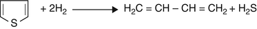
Thiophene
-
Step (1)
-
Step (2)
$$ {\mathrm{H}}_2\mathrm{C}=\mathrm{C}\mathrm{H}-\mathrm{C}\mathrm{H}={\mathrm{CH}}_2+2{\mathrm{H}}_2\to {\mathrm{H}}_3\mathrm{C}-{\mathrm{CH}}_2-{\mathrm{CH}}_2-{\mathrm{CH}}_3 $$

Benzothiophenes

Dibenzothiophenes

Most of the reactions are straightforward, with the exception of the hydrodesulfurization of aromatic sulfur species. This reaction is more complex, since several routes are possible: direct desulfurization, or hydrogenolysis to a biphenyl species, hydrogenation of one aromatic ring followed by hydrogenolysis, and isomerization of sterically hindering alkyl groups in the 4- and/or 6- positions followed by the preceding pair of reactions. The latter of the three mechanisms is not depicted. The relative rate of hydrogenolysis in the second step is much faster than the hydrogenation in the first step (Dugulan et al. 2008).
Shown below is a ranking of the six sulfur types ranked on the basis of ease of removal:
-
Easiest to remove → hardest to remove
-
Mercaptans → sulfides → disulfides → thiophenes → benzothiophenes → dibenzothiophenes
The relative ease of removing sulfur from a particular hydrocarbon fraction depends greatly on the sulfur types present. In naphtha fractions, much of the sulfur is present as mercaptans and sulfides, which makes for relatively easy sulfur removal. In gas oil fractions, the majority of the sulfur is present as benzothiophenes, naphthobenzothiophenes, and dibenzothiophenes. Hence, the sulfur is much more difficult to remove from gas oils than from naphtha fractions. And the more difficult sulfur species are found in the heavier fractions, which means that heavy gas oils are more difficult to treat than light gas oils (Fig. 5).

Relative reaction rates of selected sulfur species
Nitrogen Removal
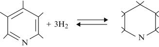
Nitrogen is mostly found in the heaviest end of petroleum fractions in five- and six- membered aromatic ring structures. Both the molecular complexity and quantity of nitrogen-containing molecules increase with increasing boiling range, making them more difficult to convert. The hydrodenitrogenation reaction proceeds through a different path from that of desulfurization. In hydrodesulfurization, the sulfur is removed first and the resulting intermediate olefin is saturated; in hydrodenitrogenation, the aromatic ring is saturated first and then the nitrogen is removed. This is shown below.
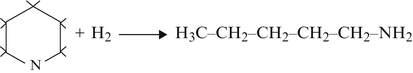
Denitrogenation Mechanism
-
(a)
Aromatic hydrogenation
-
(b)
Hydrogenolysis
-
(c)
Hydrodenitrogenation
$$ {\mathrm{H}}_3\mathrm{C}-{\mathrm{CH}}_2-{\mathrm{CH}}_2-{\mathrm{CH}}_2-{\mathrm{CH}}_2-{\mathrm{NH}}_2+{\mathrm{H}}_2\to {\mathrm{H}}_3\mathrm{C}-{\mathrm{CH}}_2-{\mathrm{CH}}_2-{\mathrm{CH}}_2-{\mathrm{CH}}_3+{\mathrm{NH}}_3 $$


Some typical examples of denitrogenation reactions are shown below:
-
(a)
Amine
$$ {\mathrm{H}}_3\mathrm{C}-{\mathrm{CH}}_2-{\mathrm{CH}}_2-{\mathrm{CH}}_2-{\mathrm{NH}}_2 + {\mathrm{H}}_2\to\ {\mathrm{H}}_3\mathrm{C}-{\mathrm{CH}}_2-{\mathrm{CH}}_2-{\mathrm{CH}}_3 + {\mathrm{NH}}_3 $$ -
(b)
Pyrrole

-
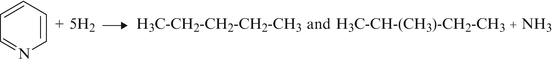
(c)
Pyridine
-
(d)
Quinoline
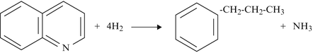


Nitrogen is more difficult to remove and consumes more hydrogen than sulfur removal because the reaction mechanism often requires aromatic ring saturation prior to nitrogen removal. Hydrogenation of associated aromatic ring structures is very dependent on hydrogen partial pressure and is the rate-limiting reaction step in nitrogen removal. Nitrogen removal is therefore strongly dependent on hydrogen partial pressure.
Oxygen Removal
Most petroleum crudes contain low levels of oxygen. The oxygen-containing compounds are converted, by hydrodeoxygenation, to the corresponding hydrocarbon and water. The lower-molecular-weight compounds are easily hydrodeoxygenated; however, the higher-molecular-weight compounds – e.g., furans – are more difficult to convert. Shown below are typical examples of hydrodeoxygenation:
Phenols

Oxygenates
Naphthenic acids

Olefin Saturation
Olefins are not found in petroleum, but are formed when processed in thermal or catalytic units. In general, fractions containing olefins are unstable and thus must be protected from contact with oxygen prior to hydrotreating to prevent the formation of polymer gums. That is especially true of feedstocks derived from thermal cracking operations such as coking and ethylene manufacturing, or naphtha cracking. Typical olefin saturation reactions are shown below:
Hexene
Cyclohexene

Olefin saturation reactions are very rapid and highly exothermic. While the hydrodenitrogenation reaction shows a heat of reaction of 1 Btu/lb of feed for each 100 ft3 of hydrogen consumed and the hydrodesulfurization reaction generates 1 Btu/lb of feed for each 10 ft3 hydrogen consumed, the olefin saturation generates 1 Btu/lb of feed for each 2 ft3 of hydrogen consumed. If proper care is not exercised during operations, it can result in flow obstructions, such as excessive coking that can lead to pressure drop buildup and/or poor liquid flow distribution through the catalyst bed(s). Diolefins are readily hydrogenated to olefins at low temperatures, e.g., <375 °F.
Aromatic Saturation
Saturation of aromatics is desirable for improvement of the properties of petroleum products, e.g., smoke point, diesel index, etc. The aromatics found in the naphtha to gas oil boiling range are present as one-, two-, and three-ring aromatics – often referred to as mono-, di-, and tri-aromatics. Typical reactions are shown below:
One ring – toluene

Two rings – naphthalene

Three rings – phenanthrene

The reactions shown above provide the mechanism by which polyaromatic compounds saturate, via a stepwise mechanism: from tri-aromatics, to di-aromatics, to mono-aromatics. The end products are naphthenic. Ring opening does not occur in hydrotreating (it does in hydrocracking) because a hydrotreating catalyst’s support is not designed with significant acidity, unlike a hydrocracking catalyst. The aromatic saturation reaction is strongly favored by high hydrogen partial pressure. Unlike all the other hydrotreating reactions, the amount of conversion of aromatics becomes equilibrium limited at higher operating temperatures within the commercial operating range, since the naphthene dehydrogenation reverse reaction becomes favored when temperature is increased. The optimum temperature for maximum aromatic saturation depends on LHSV, hydrogen partial pressure, and catalyst type but typically lies in the range of 670–730 °F.
Mono-aromatic rings are much more difficult to saturate than the di- and tri-aromatic rings because the saturation of the last aromatic ring requires the most energy. This means that as aromatic saturation proceeds, there is little progress in total aromatics reduction until most, if not all, of the di- and tri-aromatics have been saturated. The complete saturation of aromatics requires the application of noble metal catalysts in a sulfur- and H2S-free environment and is generally not possible in conventional hydrotreating with base metal sulfide catalysts.
Metals and Nonmetal Removal
Most metallic contaminants are present as organometallic compounds. Once deposited, these metals contribute to catalyst deactivation; unlike coke, they cannot be removed by regeneration. In naphtha hydrotreating, the most commonly occurring contaminants are arsenic from certain crude sources, alkali metals (e.g., Ca, Na), mercury from certain condensates, and silica from polydimethylsiloxane-based antifoam agents used in visbreakers, delayed cokers, and deepwater drilling for crude oil. Gas oil streams may contain traces of nickel and vanadium in the heavier fractions. These too are deposited on the catalyst and contribute to deactivation. Atmospheric residua can contain metals, almost exclusively Ni and V, in the 20–500 ppm range. Hydrodemetallation of that type of feedstock is an important goal of processing and special hydrodemetallation catalysts are applied for that purpose. Hydrodemetallation of nickel and vanadium occurs before any substantial hydrodesulfurization and conversion of the feedstock take place:
Arsenic trapping catalysts, necessary for trapping organo-arsine contaminants such as triethylarsine, are typically NiS based. These trapping catalysts rely on arsenic binding with NiS to form nickel arsenides. Higher operating temperatures lead to greater arsenic pickup. In the case where arsenic and silica are both present, it is advantageous to utilize a moderate concentration of Ni, as in 10–15 wt%, so that the trapping catalyst will still have sufficient surface area to trap silica.
Alkali metals can originate from various crudes, from mis-operation of the crude desalter, and from various operations which utilize caustic soda. Alkali metals adsorb to the acid sites of the catalyst support, reducing activity. Their presence may also be indicated by a rapid increase in pressure drop, especially in the layers above the primary hydrotreating catalyst(s). During catalyst regeneration, the presence of alkali metals tends to sinter the catalyst surface, resulting in surface area loss beyond what is typically observed.
Mercury contaminants can generally be classified as hydrocarbon soluble, water soluble, and asphaltenic. These can be found, in various proportions, within those crudes extracted near tectonic plate boundaries. Elemental mercury and alkyl-mercury compounds will exit a crude column with the product streams according to their relative volatility, from the LPG through to the heavy diesel. Water-soluble mercury would be found in the heels of crude storage vessels and in the aqueous drawoff from desalters. Asphaltenic mercury can be found in the atmospheric resid and vacuum resid refinery streams. Asphaltenic mercury can be converted to the lighter, hydrocarbon-soluble forms of mercury through hydroprocessing, which can be problematic for an equipment that processes finished product streams, since elemental mercury will form amalgams with Cu-containing alloys and with equipment constructed at least in part of aluminum, leading to embrittlement failures. In general, mercury is not substantially trapped by typical hydrotreating catalysts, so installation of a posttreat bed of mercury-trapping adsorbent may be needed to prolong downstream equipment life and to otherwise satisfy market requirements (Hadden et al. 2010).
Silica guard catalysts, loaded above the primary HDS catalysts in naphtha hydrotreaters, are designed with high surface area. These catalysts are often designed with a modest hydrogenation function via the NiMoS active phase. The heat release of hydrogenation in this reactor drives the silica capacity higher than an equivalent silica guard support without a NiMoS active phase. The adsorption mechanism is directed by the available surface area and the operating temperature, such that higher temperatures and surface areas result in greater silica capacities. Silica adsorption can be tracked by proxy via the regular monitoring of the hydrodenitrogenation performance, rather than the hydrodesulfurization performance. Several products of polydimethylsiloxane decomposition have been identified. It has been proposed that the decomposition products’ silanol groups react with the alumina support hydroxyl groups (Chainet 2012).
Halide Removal
Organic halides, such as chlorides or bromides, can be present in petroleum fractions at trace levels. Under hydrotreating conditions, organic halides are largely converted to the corresponding hydrocarbon and hydrogen halide. The typical reaction is shown below:

With the above to serve as an introduction and overview, a number of important hydrotreating applications are presented below in greater detail.
Distillate Hydrotreating
As specifications for diesel fuels became ever more stringent, especially with regard to sulfur but also with regard to aromatics and density, improved hydrotreating technology is needed to satisfy the new specifications. This has led to the development of ever more active catalysts, e.g., Type II hydrotreating catalysts, and an intensification of research and development efforts aimed at improving hydrotreating fundamentals understanding.
Catalytic Chemistry of Diesel Desulfurization
Full-range diesel has a rather broad boiling range, from ~300 °F to ~700 °F, and contains a very broad range of sulfur compounds ranging from lower-molecular-weight alkyl sulfides and benzothiophenes through dibenzothiophene, substituted dibenzothiophenes, and higher-molecular-weight naphthobenzothiophenes. Generally, all sulfur compounds boiling lower than 4-methyldibenzothiophene undergo rapid desulfurization at conditions required for production of 10 wppm sulfur diesel (ULSD).
Examples of typical sulfur compounds found in diesel fuels are presented below, ranging from the easiest sulfur compounds to convert to the most difficult:


The most difficult sulfur compounds to desulfurize are the substituted dibenzothiophenes, especially those where the substituent is adjacent to the sulfur atom, in the 4- position or in the 4- and 6- positions for the case of double substitution. These compounds, such as 4-methyldibenzothiophene and 4,6-dimethyldibenzothiophene and similar structures, present the most difficult compounds to desulfurize.
Analytical Characterization
Approximately 10 years ago saw the introduction of a powerful new analytical technique applied to the characterization of petroleum fractions, comprehensive gas chromatography (GC), or “two-dimensional” GC, commonly referred to as GCxGC. While the description of the method may be found elsewhere, the results offer much greater insights into the chemical composition of petroleum fractions than was possible previously. A comprehensive GC 3D representation of the hydrocarbon structures present in a distillate is shown in Fig. 6.

Comprehensive GC 3D image of hydrocarbon content of distillate
The paraffinic structures appear as spikes along the x-axis with increasing molecular weight.
Single-ring aromatics appear as families of spikes angling at a 45o angle to the right, again with increasing molecular weight as one progresses to the right from one family to the next, e.g., from C3 benzenes to C4 benzenes. The larger spikes, beyond the indane “range,” are the di-aromatics (naphthalenes) again arranged in “families” of increasing molecular weight. The next, smaller, series of spikes are three-ring aromatics, followed by traces of multi-ring aromatics. All compounds may be identified and quantified to fully characterize the composition of the distillate.
A similar GCxGC analysis focusing on sulfur compounds is shown in Fig. 7.

Comprehensive GC 3D image of sulfur compounds in distillate
The type of compound is shown, e.g., thiophene, benzothiophene, or dibenzothiophene, as well as the extent of substitution on the ring.
The same can be accomplished for nitrogen species (Fig. 8).

Comprehensive GC 3D image of nitrogen compounds in distillate
Catalysts and Reactions
Both Co/Mo and Ni/Mo catalysts have been employed in the hydrotreatment of distillate fuels. While, in the early stages of development, the Ni/Mo catalysts were judged to be slightly more active in hydrodesulfurizing diesel fuels to ULSD (<10 wppm Sulfur) specifications, more recent developments have provided Co/Mo catalysts with equivalent activity to ULSD. The observations that Ni/Mo catalysts may be more active for ULSD is in accord with the theory that for the desulfurization of the most difficult sulfur molecules, dimethyldibenzothiophenes with substituent groups in the 4- and 6- positions, such as 4,6-dimethyldibenzothiophene, one of the rings needed to undergo saturation of one of the rings, allowing the sulfur atom to be more accessible due to the greater flexibility of the saturated ring. This pathway for desulfurization was termed the “hydrogenation” pathway and was most pronounced over Ni/Mo catalysts with their higher activity for saturation. The other pathway involved direct abstraction of the sulfur atom, and formation of H2S was termed the “direct abstraction” route and was the dominant route on Co/Mo catalysts.
The direct abstraction reaction is depicted below:

The “hydrogenation” pathway, in simplified form, is

followed by

There has been considerable debate as to which pathway is dominant; it is likely that both are active, although to differing degrees, on modern Type II catalysts. For the case of the “hydrogenation” pathway, it may be inferred that the reversible saturation of one ring may be limiting at low pressures. This issue was addressed by Jones and Kokayeff (Jones et al. 2005) as well as Ho (Ho 2003, 2004).
While these sulfur compounds are the most difficult to desulfurize and present the greatest challenge to achieving ULSD (<10 wppm S diesel), an additional complication is the inhibition by nitrogen compounds. While inhibition by nitrogen has been known for some time, the magnitude of the inhibitory effect can only been appreciated when deep desulfurization to ULSD levels is required.
Nitrogen Compounds
The most difficult to convert nitrogen compounds present in diesel are the carbazoles.


The carbazole compounds boil within the same boiling range as the substituted dibenzothiophenes, ~620–660 °F. At conditions that desulfurize the feed to <10 wppm S, hydrodenitrogenation is very extensive and is essentially complete.
Aromatics
Aromatic compounds are another class of compounds that are of importance in the hydrotreating of distillate fuels. Aromatic compounds may be classified in three main classes – multi-aromatics (3+ condensed rings), di-aromatics, and mono-aromatics.
2-Ethyl-7-methylanthracene

1,7-Dimethylanthracene

7-Ethyl-2-methyl-1,2,3,4,4a,9a-hexahydroanthracene

7-Ethyl-2-methyl-1,2,3,4,4a,9,9a,10-octahydroanthracene

Saturation reactions of aromatic compounds proceed sequentially

The saturation reactions are exothermic and reversible. These reactions consume hydrogen (not shown) but also improve the quality of the diesel fuel by increasing the cetane number; therefore, they are not necessarily undesirable, and distillate hydrotreater pressures and catalyst choices are sometimes dictated by the desire to achieve a given cetane number. Additionally, there is evidence that aromatics may inhibit the desulfurization of the most difficult, sterically hindered dibenzothiophenes, sulfur species (Jones et al. 2004).
Feedstocks
Feed to a distillate hydrotreating unit may be any blend or combination of straight-run distillate (SRD), coker distillate (LCGO), and light cycle oil (LCO).
Straight-run distillate is, as the name implies, derived from the distillation of crude oil and is the cut obtained crude column, boiling in the range of ~300 °F to ~730 °F. Straight-run distillates are characterized by high API gravities, in the range of 28–32 and sometimes higher and low levels of sulfur (0.5–1.5 wt%), nitrogen (40–100 wppm), and aromatics (usually <20 wt% total).
Coker distillates, while boiling in the same range as straight-run distillates, are derived from coking operations and differ from straight-run distillates in that they contain greater amounts of sulfur (up to 2.5–3.0 wt are possible), higher levels of nitrogen (500–1,500 wppm), and somewhat higher aromatics content. The additional feature that sets them apart is the presence of olefins (typically measured as a bromine number) with a bromine number of 10–30. Due to the olefin content and the higher aromatics content of coker distillates, their processing in a hydrotreater is accompanied by a significant temperature rise due to the exothermic saturation reactions of olefins and aromatics. Finally, the presence of fragments of the Si-based antifoam agent used in cokers will deactivate the hydrotreating catalysts processing the coker streams.
Light cycle oils are characterized by low gravities (API gravities in the range of 12–22) and high levels of aromatics. Aromatics levels in LCOs may be as high as 70 wt% with the di-aromatics being the most prevalent. A typical aromatics distribution of an LCO containing 70 wt% aromatics may be 10 wt% mono-aromatics, 45 wt% di-aromatics, and 15 wt% tri-aromatics. The concentration of sulfur in an LCO may range from ~500 wppm (for an LCO derived from an FCC with an FCC feed pretreater) to ~2 wt% for FCC units processing high-sulfur feeds without a FCC feed pretreater. Nitrogen levels are not usually very high, reaching into several hundred wppm. Processing LCO in a hydrotreater is accompanied by high hydrogen consumption due to the saturation of the aromatic compounds and high heat release and temperature rise due to the exothermic nature of the saturation reactions. Temperature control is important due to the rapid saturation rate of the multi-ring aromatics.
Process Configuration
A simplified process flow diagram of a distillate hydrotreater is shown in Fig. 9.

Simplified process flow diagram of a distillate hydrotreater
The feed enters the feed surge drum from which it is pumped through a bank of feed/effluent exchangers, is mixed with recycle gas, is heated to reaction temperature, and enters the reactor. Reactor effluent is passed through a bank of feed/effluent exchangers and a fin fan cooler and then enters the separator. The gas is recovered and sent to an amine scrubber to remove hydrogen sulfide and ammonia and then routed to a recycle gas compressor and recycled to the reactor. The liquid product is then directed to a flash drum, where any light gases are recovered overhead while the hydrocarbon is routed to a stripper to remove any dissolved hydrogen sulfide and ammonia in the product as well as any wild naphtha formed. The stabilized product is then sent to blending or storage. Wash water is added to the reactor effluent just upstream of the air fin cooler to absorb the ammonia produced in order to avoid precipitation of ammonium hydrosulfide salts in the colder sections for the plant.
The process flow diagram shows one quench location between two catalyst beds. The number of beds and quenches will depend on the type of feed being processed with SR distillates requiring only one point while LCGOs and LCOs requiring three or more beds with interbed quenches to control temperature rise.
Process Conditions
Process conditions applied in distillate hydrotreating today are much more severe than they were in the past. This is due primarily to the requirement to produce ULSD (ultra-low-sulfur diesel, i.e., with a sulfur level <10 wppm). Typical process conditions are shown in Table 1.
The variation in process conditions is due to a number of factors including feedstock characteristics, such as sulfur content and nitrogen content, feedstock type, and process objective: hydrodesulfurization to ULSD levels and/or cetane improvement. Note that conditions to effect significant improvements in cetane are usually sufficient to produce ULSD sulfur specifications.
Naphtha Hydrotreating
Introduction
Naphtha is a general term that refers to the lightest liquid fraction of material in the refinery. A full boiling range naphtha typically has an initial boiling point of 85 °F (30 °C) and a final boiling point ranging from 380 °F to 420 °F (193–215 °C), which roughly corresponds to C5 through C12 material. The back-end cut point of full boiling range naphtha ultimately depends on the individual refinery’s configuration and whether the objective is to maximize gasoline, diesel, or petrochemical feedstock production.
Straight-Run Versus Cracked Naphtha
Naphtha can be broadly categorized as either straight-run or cracked naphtha. Stabilized naphtha from the crude column is referred to as straight-run material, since it has not been exposed to any severe thermal or catalytic process conditions and therefore has a negligible olefins content. In contrast, naphtha produced from a carbon rejection process, such as a coking or fluidized catalytic cracking, is considered a cracked stock and will contain a significant olefins content. More specifically, cracked naphtha will contain both monoolefins and diolefins; the reactivity of these olefin species requires specific design considerations.
This section will primarily focus on straight-run and coker naphtha, since these two streams often share the same disposition in the refinery. When producing gasoline, refiners tend to handle FCC naphtha differently, since it has a relatively higher octane value and therefore it requires selective desulfurization to meet final gasoline product sulfur specifications.
In addition to the difference in olefin content, straight-run naphtha contains less sulfur and nitrogen than its coker naphtha counterpart from the same crude source. Furthermore, coker naphtha also contains silicon due to the use of antifoaming agents in the upstream coking unit, which can negatively affect hydrotreating catalyst as well as catalysts in downstream operating units, such as a naphtha reforming process.
Table 2 provides an example of typical properties of straight-run naphtha compared to that of coker naphtha.
Naphtha Disposition
For refineries that produce gasoline, the inherent octane values of the straight-run and coker naphtha stream are too low to allow blending of the entire stream into the gasoline pool. To ensure that the naphtha stream can be fully utilized for gasoline production, the refiner will send the naphtha stream to a catalytic naphtha reforming unit to increase the stream’s octane value, primarily via dehydrogenation of naphthenes to aromatics. Prior to being processed in the reforming unit, the naphtha stream needs to be effectively hydrotreated to minimize the presence of organic sulfur, nitrogen, other trace contaminants, and olefins to avoid poisoning of the precious metals reforming catalyst and fouling its continuous regenerator. The final liquid product from the reforming unit is often referred to as reformate and can be used as a low-sulfur (sulfur-free), high-octane gasoline blend component.
Alternatively, some refiners choose to minimally hydrotreat their naphtha stream and sell the lightly treated naphtha on the market as feedstock for petrochemicals production. In areas with high bitumen crude production, naphtha can also be utilized as a diluent to improve the properties of bitumen crude for transportation.
Processing Objectives and Considerations
Table 3 summarizes the recommended hydrotreated naphtha quality for feed to a naphtha reforming unit.
In order to achieve the reformer feed quality, the below contaminant removal reactions need to take place in the presence of the appropriate grading material and hydrotreating and under the right set of process conditions. In the era of leaded gasoline, gasoline re-run through the naphtha hydrotreater also required hydrodemetallation to prevent lead and other metals from poisoning the naphtha reforming catalyst.
Desulfurization (HDS for hydrodesulfurization) difficulty depends on the type of sulfur molecule, such as mercaptan, sulfide, thiophenol, thiophene, or benzothiophene sulfur. Relatively, mercaptan sulfur is the easiest type of sulfur to remove, whereas benzothiophene is approximately 15 times harder to remove than mercaptan sulfur. Sulfurs contained in an aromatic structure are removed by initially opening the ring, removing the sulfur molecule, and saturating the resulting olefin molecule.
Denitrogenation (HDN for hydrodenitrogenation) is generally more difficult than desulfurization due to the structure of the nitrogen compound. Nitrogen contained in an aromatic structure is removed via a different mechanism than sulfur contained in an aromatic compound. In denitrogenation, the aromatic ring is first saturated, then the ring is cleaved, and finally the nitrogen molecule is removed. Since aromatic saturation is required to remove aromatic bound nitrogen, the design pressure of the hydrotreating unit is more sensitive to the nitrogen content of the feed rather than the sulfur content of the feed.
Olefin saturation is a relatively rapid reaction that occurs alongside with desulfurization and denitrogenation. There are two main types of olefins to consider when processing cracked naphtha stock: diolefins or dienes (molecules containing two double bonds) and monoolefins (molecules containing a single double bond).
Dienes can potentially polymerize and form gums if introduced to hydrotreating catalyst and hydrogen at the typical temperatures required for hydrodesulfurization and denitrogenation. Gum formation can either occur in feed heat exchangers or at the top of the first reactor catalyst bed, leading to fouling and pressure drop issues, which could ultimately lead to an unplanned unit shutdown and shortened cycle length.
For combined naphtha streams with a significant amount of diene content, the stream can first be treated in a separate diolefin saturation reactor to minimize the risk of gum formation. The diolefin reactor utilizes a relatively low-activity hydrotreating catalyst and operates within a low enough temperature range to ensure the diolefin saturation reaction preferentially occurs instead of the polymerization reaction. After the dienes are stabilized, the naphtha stream can then be heated up and sent to a second reactor loaded with the main hydrotreating catalyst to complete the removal of sulfur and nitrogen.
Once the diene content of a cracked naphtha blend is addressed, the next consideration focuses on the monoolefin molecules. The olefin saturation reactions occur fairly rapidly in the main hydrotreating reactor and result in a substantial amount of heat release. The reaction occurs so readily that at start of run conditions the majority of the olefins are saturated within the first bed of a hydrotreating reactor, resulting in a significant heat rise across the first bed, and smaller temperature rises in the following bed. It is important to manage the heat released due to olefin saturation in order to prevent coking, catalyst sintering, or uneven catalyst utilization across the different catalyst beds. This can be achieved by recycling some of the olefin-free reactor product with the fresh feed in order to dilute the olefins available for saturation. Ultimately, the proper management of olefin heat release is required to achieve the desired catalyst cycle length in the main hydrotreating reactor.
Potential for Recombination with Cracked Stock
Due to presence of olefins in coker naphtha material, the potential for mercaptan recombination exists. The below equation describes the equilibrium between mercaptans and olefin and H2S present in the reactor. It is desirable to favor the left-hand side of the equation so that the sulfur content from the feed is present in the off-gas from the unit instead of the liquid product. This can be done by installing a relatively small posttreat reactor that operates at a lower condition than the main hydrotreating reactor, which favors the left-hand side of the equation and reduces the amount of mercaptan sulfur than can be found in the hydrotreated naphtha material:
Typical Operating Conditions
Table 4 compares the general range of operating conditions for the main hydrotreating reactor for both a straight-run naphtha hydrotreating unit and a coker naphtha hydrotreating unit.
Pressure
Hydrotreating feeds with a significant amount of coker naphtha material typically contain higher amounts of nitrogen, which requires the hydrotreating reactor to operate at higher pressures to ensure the appropriate denitrogenation reactions take place to meet the 0.5 wppm nitrogen specification for reformer feed.
LHSV
In addition to higher sulfur and nitrogen contaminant levels in coker naphtha feed blends, the presence of Si also requires the addition of trapping material, which lowers the liquid hourly space velocity (LHSV) in the hydrotreating unit. Liquid hourly space velocity is the liquid feed rate divided by the catalyst volume and is expressed in units of inverse time. LHSV is inversely proportional to the liquid residence time in the catalyst. The amount of Si trap required depends on the concentration of Si in the feed blend, the trapping capacity of the hydrotreating catalyst or guard material, and the desired cycle length:
Gas-to-Oil Ratio
A minimum H2 partial pressure in the reactor is required to ensure reasonable rates of reactions and additionally to prevent possible coking of the catalyst. As summarized in the table above, higher levels of contaminants require higher levels of gas-to-oil ratio in the hydrotreating unit.
The gas-to-oil ratio is calculated as follows:
Diene Reactor
A diene reactor typically operates with a LHSV varying from 3 to 6 h−1 and a gas-to-oil ratio ranging from 250 to 1,000 scf/bbl (40–170 Nm3/m3).
Posttreat Reactor
The posttreat reactor LHSV can range from 12 to 18 h−1. Since the total reactor effluent is sent to the posttreat reactor prior to any gas-liquid separation, treat gas is primarily introduced as a quench to ensure the posttreat reactor operates at a low enough temperature to favor the formation of H2S and a saturated hydrocarbon over the formation of a mercaptan. For additional assurance of satisfying naphtha reforming and paraffin isomerization feed sulfur requirements, a sulfur guard can be applied to treat the stabilized product. NiS-based adsorbents are typically applied in sulfur guard bed services.
Process Configuration
Figure 10 provides a simplified flow diagram of a straight-run naphtha hydrotreating unit. Typically a recycle gas scrubber is not required when hydrotreating straight-run naphtha alone. The stabilized product from the bottom of the stripper unit can either be sent directly to the reforming unit as feed or be split into light and heavy naphtha portions in a downstream naphtha splitter.

Simplified process flow diagram of a naphtha hydrotreater
Figure 11 presents a simplified flow diagram of a typical coker naphtha hydrotreating unit . Additional pieces of equipment are required to address the higher levels of sulfur and nitrogen contaminant as well as the presence of olefins in coker naphtha material. As discussed earlier, the coker naphtha hydrotreating unit will also contain a diene reactor and a posttreat reactor. Another differentiating feature in the coker naphtha flow scheme is the recycle of treated product with fresh feed to manage the exotherm in the main hydrotreating reactor. Lastly, a recycle gas scrubber will typically be specified to remove H2S and NH3 from the recycle gas stream to minimize inhibition of catalyst activity in the main hydrotreating reactor.

Simplified process flow diagram of a coker naphtha hydrotreater
Desulfurization of FCC Gasoline
Introduction
While hydrotreating of most other feedstocks is characterized by a desire for the most active catalyst to effect a given conversion (whether of sulfur, nitrogen, or aromatics), the case of desulfurization of FCC gasoline is unique in that it is characterized by selectivity rather than activity considerations. Specifically, it is desired to reduce the sulfur level to the required specification while minimizing the saturation of olefins and subsequent octane loss.
Composition of FCC Gasoline
FCC gasoline is composed of n-paraffins, i-paraffins, n-olefins, i-olefins, cyclic olefins, naphthenes, and aromatics. The desirable, high-octane, components are olefins and aromatics and, to a lesser extent, i-paraffins.
Sulfur compounds present in FCC gasoline include mercaptans, sulfides, and thiophenes as well as benzothiophenes. While these compounds do have differences in reactivity, i.e., some undergo desulfurization more easily than others, the differences in reactivity are not nearly as pronounced as observed for sulfur compounds present in distillates. The most difficult sulfur compounds to desulfurize in FCC gasoline are thiophenes with substituent groups in the 2- position, e.g., 2-thiophene, 2-ethylthiophene. 2,5-dimethyl thiophene, and 2-ethyl-5-methyl thiophene. While these compounds may be more difficult to desulfurize than the sulfides and mercaptans, the greatest complicating factor in the desulfurization of FCC gasoline is recombination, i.e., the formation of mercaptans from the olefins present in the feed and the H2S formed during desulfurization.
Recombination
Recombination is the name applied to the reaction of olefins with H2S to form mercaptans:
Recombination is a reversible reaction that approaches equilibrium at conditions used to effect desulfurization. It is an exothermic reaction and becomes less favorable with increasing temperature. To fully appreciate the complications caused by this reaction consider the following expression for the equilibrium between the species involved, olefins, H2S, and mercaptans:
This may be rewritten as
where WRSH is the weight fraction (in wppm) of mercaptan in the liquid hydrocarbon, Wo is the weight fraction of olefins in the liquid hydrocarbon, PH2S is the partial pressure of H2S, K is the equilibrium constant, and f is a conversion factor.
The amount of recombinant mercaptan remaining in the liquid hydrocarbon is dependent upon the concentration of olefins present and the partial pressure of H2S. One may simplify this a bit further for clarity as follows:
where WFS is the sulfur content of the feed, in wppm.
What can be gleaned from this is that the amount of recombinant mercaptan that will remain in the gasoline is dependent on the weight fraction of olefins and the sulfur content of the feed, where it was assumed that all the sulfur content originally present in the feed is converted to H2S. The higher the olefin content of the product (it is desired to preserve olefins) and the higher the sulfur content of the feed, the higher the recombinant mercaptan sulfur that will remain in the gasoline, thus placing a limit on the extent of “desulfurization” that is possible to achieve.
An additional complication arising from recombination is the loss of olefins by the desulfurization of the mercaptans:
Thus, while the formation of recombinant mercaptans is a reversible, equilibrium-dominated reaction, there is also the “drainage” reaction, the desulfurization of the mercaptan, which, in combination, provides an alternate path for olefin loss in addition to the conventional olefin saturation reaction. Complications presented by the recombination reaction in FCC gasoline desulfurization are covered by Leonard and Kokayeff (Leonard et al. 2006).
Process Considerations
The three main process licensors of hydrotreating technology for processing FCC gasoline are ExxonMobil (SCANfining™ Process), IFPEN/Axens (Prime-G+™ process), and Honeywell UOP (SelectFining™ Process). While all three process licensors offer a number of different flow schemes based on feed characteristics, e.g., sulfur level, and product targets, these technologies have much in common.
Saturation of Diolefins
Besides olefins, FCC gasoline contains diolefins which may cause fouling of heat exchanger surfaces as well as pressure drop in the hydrotreating reactor and catalyst deactivation by deposition of coke. The removal of diolefins is accomplished in a similar manner as is done for coker naphtha hydrotreaters, i.e., by processing the feed at mild conditions over a hydrotreating catalyst. This simple procedure effects the saturation of diolefins to monoolefins. In the Axens Prime-G+™ process, this step contains a catalyst that is also active for the reaction of mercaptans with olefins to form thioethers:
The thioether boils at a much higher temperature than the mercaptan, thus allowing for the conversion of low-boiling, low-molecular-weight mercaptans to be converted to much higher-boiling sulfur compounds. This allows for the separation of the light cracked naphtha (LCN) which is sulfur-free and contains C5 and C6 olefins from the sulfur-rich, higher-boiling portion of the feed, which needs to be processed. The benefit is that the removal of these olefins preserves them from undergoing saturation in the hydrotreating reactor and also allows for a lower olefin content of the stream that is hydrotreated, thus allowing for the attainment of lower sulfur levels while minimizing octane loss due to olefin saturation.
Desulfurization
A common feature to all the process licensors is the selective desulfurization reaction of the FCC gasoline carried out over a catalyst specifically designed to effect desulfurization with minimal saturation of olefins. In all cases, the feed to the selective desulfurization reactor has been processed in a DIOS (diolefin saturation reactor) to saturate the diolefins. In some cases, the effluent of the DIOS may be split into two in a splitter with the splitter overhead (LCN) either being sulfur-free (Prime-G+™) or being subjected to a mercaptan extraction process (e.g., Merox or Exomer) and the splitter botts then routed to the selective desulfurization reactor.
Reactions occurring in the selective desulfurization reactor include:
Desulfurization
Olefin saturation
Recombination
Olefin drainage
While all these reactions are exothermic, the catalysts are so selective that desulfurization takes place to a much greater degree than olefin saturation, and hence the temperature rise can be kept to manageable levels.
Process Configurations
The simplest process configuration consists of a DIOS followed by a selective desulfurization reactor and a product stripper to remove H2S (Fig. 12).

Simplified process flow diagram of an FCC gasoline desulfurization unit – single stage
Such a simple process configuration would be satisfactory when feed sulfur levels are low, typically less than ~300 wppm. In such cases, it is possible to achieve very low product sulfur levels, <10 wppm, with minimal saturation of olefins and good octane retention.
A more complex process configuration would be required when the feed sulfur content is higher than ~300 wppm. In this case, the feed is first routed to a DIOS reactor to saturate the diolefins with the effluent of the DIOS entering a splitter with the LCN sent overhead and the bottoms routed to a selective desulfurization reactor. The splitter overhead may be subjected to a process such as UOP’s Merox Process™ to extract the light mercaptans (Fig. 13).

Simplified process flow diagram of an FCC gasoline desulfurization unit – single stage with extractive Merox Process™
A modification of the above process is Axens Prime-G+™, wherein the thioetherification function inherent in the diolefin saturation/selective hydrogenation catalyst, or SHU™, is also applied. The light mercaptans are converted to higher-boiling sulfides by reaction with olefins. The sulfides thus formed boil at a much higher temperature and appear in the splitter bottoms and are subsequently desulfurized in the selective desulfurization reactor(s). The effluent from the SHU™ reactor is routed to a splitter which separates the light cracked naphtha (LCN) as an overhead product which is essentially sulfur-free. The splitter bottoms is routed to the selective desulfurization reactors HDS-1 and HDS-2 (Fig. 14). The second desulfurization reactor operates at a higher temperature. Decomposition of the remaining sulfur compounds, due to the higher temperature, limits the remaining recombinant mercaptans to meet the desired sulfur specification.

Simplified process flow diagram for FCC gasoline desulfurization
At high feed sulfur levels, the amount of H2S produced is so high, and the formation of mercaptans is so extensive that low product sulfur levels cannot be achieved without separation of the H2S between two stages of desulfurization. This type of flow scheme is represented below by two-stage SelectFining (see Fig. 15). The FCC gasoline enters the DIOS reactor to saturate diolefins. The effluent of the DIOS reactor is mixed with recycle gas, heated to reaction temperature, and routed to the first selective desulfurization reactor. The effluent of the first desulfurization reactor is cooled, stripped of H2S, mixed with recycle gas, heated to reaction temperature, and routed to the second selective desulfurization reactor. Finally, the effluent of the second selective desulfurization reactor is stripped of H2S and routed to product blending/storage.

Simplified process flow diagram of a two-stage SelectFining process unit
Process Conditions
Typical process conditions are shown in Table 5.
FCC Feed Pretreating
Hydrotreating the feed to an FCC is usually practiced to remove sulfur and limit SOx emissions but also impacts the FCC in other ways. Hydrotreating the feed to the FCC results in hydrogen addition to the feed due to saturation of aromatics, thus rendering the resulting molecules easier to crack in the FCC and increasing conversion and gasoline yield. An additional benefit is the reduction in the sulfur content of the FCC gasoline, thus reducing the severity required of the FCC gasoline posttreater and consequently limiting olefin saturation and octane loss.
FCC feedstocks are vacuum gas oils boiling in the range of ~650–1,100 °F. Sulfur levels may vary widely from ~0.5 to 3 wt%. Nitrogen levels may vary from 500 to 3,000 wppm. Additionally, depending on the end point, metals (Ni and V) may also be present. While decreasing the sulfur content of the FCC feed has beneficial effects, reducing the nitrogen content and adding hydrogen will increase conversion and gasoline yield.
Feedstock Characteristics
Generally the chemical nature of the FCC feed is similar to that of distillates but of higher molecular weight.
Sulfur Compounds
Sulfur compounds , even in structures without rings, are more complex higher in molecular weight and may contain more than one sulfur atom:
7-Ethyl-2-(4-ethylheptyl)-3-propyldodecanethiol

2-(4-Ethyl-5-methylhexyl)-3,5-dimethyl-8-(3-methylpentylthio)nonanethiol

Similarly, structures containing rings are also larger, more complex, and higher in molecular weight:
7-(2,3-Dimethylpentyl)-2-isobutyl-1-methyl-9-thiafluorene

Analytical Characterization
As described in the section on distillate hydrotreating, comprehensive GC has become a very valuable tool in the characterization of the composition of vacuum gas oils. A comprehensive GC 3D image of the hydrocarbon composition of a VGO is shown in Fig. 16.

Comprehensive GC 3D image of hydrocarbon compounds in a VGO
The saturates all appear along the x-axis with increasing boiling point. Aromatic compounds appear as “families,” mono-aromatic, di-aromatic, tri-aromatic, and 4+ ring aromatic structures, of peaks according to the extent of substitution of the ring.
A similar 3D representation of the sulfur species present in a VGO appears in Fig. 17

Comprehensive GC image of sulfur compounds in a VGO
. The sulfur compounds appear as families of thiophenic structures with increasing numbers of both aromatic rings (polarity) and substitution (boiling point).
The characterization of the VGO by these methods allows for much more accurate determinations of reactivity and the application of the optimal catalysts and process conditions to effect the desired conversion.
Catalysts and Reactions
Both Co/Mo and Ni/Mo catalysts have been applied in the hydrotreatment of FCC feed. Co/Mo catalysts are sufficiently active for desulfurization at lower pressures, while Ni/Mo catalysts are more active for denitrogenation and saturation of aromatic rings at higher pressures, both of which increase the activity of the FCC catalysts and increase gasoline yield. Tri-metallic catalysts that provide average activities for all functions (hydrodesulfurization, hydrodenitrogenation, and aromatics saturation) have also been successfully applied.
Hydrodesulfurization, hydrodenitrogenation, and saturation reactions are similar to those occurring in distillate hydrotreating except the reacting species are of higher molecular weight.
Feedstocks
Feedstocks to an FCC feed pretreating unit may include vacuum gas oils (VGO) as well as heavy coker gas oil (HCGO). Sulfur contents may range from 0.5 to 3 wt% and nitrogen from 500 to 3,000 wppm. The higher values, especially for nitrogen, are found in HCGO. HCGO additionally contains olefins with bromine numbers ranging up to ~20. The olefinic nature of the HCGO feed requires consideration of catalyst bed distribution and temperature management due to the highly exothermic nature of the very rapid olefin saturation reactions.
Process Configuration
A simplified process flow diagram of a typical FCC feed pretreater is shown in Fig. 18

Simplified process flow diagram of an FCC feed pretreater
. The feed is pumped from the feed surge drum and mixed with recycle gas, and the mixture is then heated in a bank of feed/effluent exchangers and then passes to the reactor charge heater where it is heated to reaction temperature and then enters the reactor. The reactor is shown with three beds of catalyst with recycle gas being routed to the quench zones to reduce the temperature of the effluent of each bed to the desired inlet temperature of the next catalyst bed. The number of catalyst beds is dependent on the heat release and allowable temperature rise in each bed. Reactor effluent is first cooled against the combined feed or individual fresh feed and recycle gas streams in the feed/effluent exchangers and is then passed to a series of separators to recover the liquid hydrotreated hydrocarbon and the recycle gas. The recycle gas is scrubbed free of H2S in an amine scrubber and then compressed and routed back to the reactor. Water is added to the hot separator vapors to dissolve the NH3 and prevent the formation of ammonium hydrosulfide salts in the cold sections of the plant. The hydrocarbon liquid from the separator system is routed to a fractionation section to recover a wild naphtha stream, a diesel stream and the hydrotreated FCC feed.
Process Conditions
Process conditions applied in FCC feed pretreating have been getting more severe with the necessity to reduce SOx emissions from the FCC regenerator to ever lower levels. While desulfurization of the FCC feed to sulfur levels of 2,000 wppm has been acceptable in the past, the trend has progressed past 1,000 wppm sulfur to <500 wppm sulfur and recently to lower levels in efforts to minimize or eliminate the posttreatment of FCC gasoline. Typical process conditions are shown in Table 6.
The more severe (lower LHSV, higher pressure and temperature, etc.) conditions are applied to blends containing HCGO, DAO, or both. Typically the FCC pretreating unit is designed to operate with a cycle that matches the FCC turnaround cycle, which typically is 4–5 years.
Hydrocracker Pretreat
Introduction
Hydrotreating and hydrocracking share many common elements. Both processes catalytically upgrade the feedstock by adding hydrogen under moderate to high operating pressures and elevated reactor temperatures. However, a key differentiator is that hydrocracking catalysts have a stronger acid function compared to that of hydrotreating catalysts, which allows the hydrocracking catalysts to facilitate deeper cracking reactions as well as naphthenic ring-opening reactions.
A hydrocracking unit requires the use of both hydrotreating and hydrocracking catalysts to obtain the desired product qualities in the naphtha, jet, and diesel products as well as the desired operating cycle length. This section briefly touches upon the hydrotreating reactor section in the context of a hydrocracking unit.
Feedstock Types
A hydrocracking unit can be designed to handle a wide range of feedstock types. Ultimately, unit design is constrained by the economic return of processing the most severe feedstock in comparison to the associated capital expenditure and operating expense.
Vacuum gas oil (VGO) and heavy coker gas oil (HCGO) are more commonplace feedstocks for a hydrocracking unit, but as the product quality specifications for clean fuel become more stringent and the demand for transportation fuel continues to increase in lockstep with the ever-growing global population, refiners have increasingly found interest in processing feeds such as light cycle oil (LCO) from the FCC and DAO (deasphalted oil) from solvent deasphalting (SDA) units to produce high-quality fuel, such as diesel.
All four of these feedstock types will have an appreciable amount of organic sulfur (1–3 wt%) and nitrogen (500–3,500 wppm) that will need to be nearly completely removed in the hydrotreating section to protect the downstream hydrocracking catalyst from these poisons.
Light cycle oil is a highly aromatic diesel boiling range stream produced in the FCC unit. Due to the high concentration of two- and three-ring aromatics, LCO has a low cetane value, which makes it a poor blend stock for the refinery’s diesel pool. Conventional hydrotreating pressure is frequently inadequate to completely remove the native sulfur species in LCO to meet ULSD specifications. Therefore, processing the LCO in a hydrocracking unit becomes an attractive alternative. The difficult sulfur species in LCO can be more effectively removed in the high-pressure hydrotreating section of the hydrocracking unit. Furthermore, the LCO quality is further improved by the higher operating pressure of the hydrocracking unit, since additional aromatic saturation can take place to improve the cetane qualities of the stream.
Deasphalted oil is another feedstock that some refiners find economical to send to a hydrocracking unit. Processing DAO in a hydrocracking unit requires additional catalyst system considerations to account for the higher metal content (Ni and V) as well as the potential for the presence of very heavy molecules as condensed-ring aromatics. DAO is created in a solvent deasphalting unit that separates on the basis of molecular type rather than boiling point. Therefore, for moderate to heavy lifts, increasing extent of extraction, in the SDA unit the heaviest molecules in the DAO are not adequately characterized by boiling point due to the limitations of the current distillation test methods. The higher metal content in DAO is addressed by specifying an adequate amount of metal trapping material in the hydrotreating section of the hydrocracking unit. Due to the presence of very heavy molecules, the potential for a higher deactivation rate should also be considered when selecting the design operating pressure and sizing both the hydrotreating and hydrocracking catalyst beds.
Optimization Between the Hydrotreating and Hydrocracking Function
In a typical hydrocracking flow scheme, the hydrotreating section effluent is directly routed to the inlet of the hydrocracking section without any removal of the H2S and NH3 that are formed from the hydrotreating reactions. Ultimately, the catalyst loading for the hydrotreating section depends on the concentration of contaminants, organic sulfur and nitrogen, the fresh feed, and the permissible level of these contaminants entering the hydrocracking section. There is some degree of flexibility in the level of contaminants permitted to enter the hydrocracking section, particularly organic nitrogen, from the hydrotreating section. The permissible concentration will depend on the relative reactor volumes available for loading hydrotreating versus hydrocracking catalyst, the target conversion rate, and the desired product quality from the hydrocracking unit.
Residual Oil Hydrodesulfurization
Residual oil, as the name implies, is the material remaining after distillation. Atmospheric residue (AR) is the bottoms of the atmospheric column and generally has the boiling range of ~650 °F+. Vacuum gas oil is contained within AR. Vacuum residue (VR) is the bottoms of the vacuum column. With the vacuum gas oil (VGO) removed, the boiling range of the vacuum residue is ~1,050 °F+.
One of the defining characteristics of the residual oils is the presence of metals, primarily Ni and V, although smaller amounts of other metals may also be present. Ni and V are typically present in concentrations ranging from ~25 to ~1,000 wppm. Sulfur concentrations are also quite high, sometimes exceeding 3 wt%. A further defining feature of the residual oils is their high Conradson carbon residue (CCR), frequently exceeding 20 %. Additionally, the presence of condensed-ring aromatics and asphaltenes necessitates the application of high pressures and specialized catalysts to achieve reasonable cycles, typically 12–18 months.
Catalysts and Reactions
The main feature that differentiates residual oil hydrotreaters from hydrotreaters in other applications, e.g., distillate and FCC feed pretreaters, is the presence of high concentrations of metals and the necessity of removing these prior to the main hydrotreating reactors. This is accomplished by the use of specialized catalysts having larger pore diameters to accommodate the metals containing molecules (typically, but not always present in porphyrin structures; see figure below). The large pore diameters are required to allow the metal-containing molecules to penetrate to the center of the catalyst pellet rather than depositing at the pore mouth and plugging the pore, rendering it inactive despite having a “fresh” and active interior.
Vanadyl porphyrin

Nickel porphyrin

Sulfur and nitrogen atoms are also generally located in condensed-ring aromatic structures making residual oils much more difficult to process.
Process Configuration
As mentioned above, the key feature of hydroprocessing residual oils is the necessity to provide guard reactors containing large pore catalysts for the removal of metals. The guard reactors may or may not be arranged in a swing reactor system where one reactor may be taken off-line for catalyst removal and replacement while the spare reactor is placed into service. A typical process configuration of a resid hydroprocessing unit is depicted in Fig. 19. The first two reactors in fig. 19 are the “guard” reactors filled with hydrodemetallation catalysts while the remaining two are hydrodesulfurization reactors.

Simplified process flow diagram of a residual oil hydrotreater
Process Conditions
Process conditions depend on a number of factors including, feed type (AR or VR), degree of desulfurization, metals levels, carbon residue, and required cycle length. Typical process conditions are presented in Table 7.
Catalysts
Hydrotreating catalysts, in general, are high-surface-area materials consisting of an active component and a promoter, which are uniformly dispersed on a support. The catalyst support is normally gamma alumina (γ-Al2O3), doped sometimes with small amounts of silica, phosphorus, fluoride, and/or boron and prepared in such a way so as to offer a high surface area upon which to disperse the active metals and an appropriate pore structure, so that pore plugging with coke and/or metals is sufficiently mitigated to achieve the desired operating cycle. The active component is normally molybdenum sulfide, although tungsten-containing catalysts are also used (though seldom, and that generally for special applications such as lube oil processing). Regarding molybdenum catalysts, both cobalt (CoMo) and nickel (NiMo) are used as promoters. The promoter has the effect of substantially increasing (approximately 100-fold) the activity of the active metal sulfide. The acidity of the support (which itself may be increased with dopants, beyond the nascent acidity) can be increased to boost the catalyst activity for hydrocracking and isomerization reactions. The commercially available catalysts have varying amounts of promoters and active components, depending on the desired applications, but in general they can contain up to about 25 wt% promoter and up to 25 wt% active component as oxides. Hydrotreating catalysts come in different sizes and shapes and vary depending on the manufacturer (Fig. 20):

Hydrotreating catalyst shapes
Cylindrical | 1/32″–1/4″ |
Trilobe | 1/20″–1/10″ |
Quadrilobe | 1/20″–1/10″ |
Spheres | 1/16″–1/4″ |
Hollow rings | Up to 1/4″ |
Other shapes include nodular beads and wagon wheels. In general, the size and shape of the catalyst pills is a compromise between the desire to minimize pore diffusion effects in the catalyst particles (requiring small sizes) and pressure drop across the reactor (requiring large particle sizes). The physical characteristics of catalysts also vary from manufacturer to manufacturer and the intended use of the catalyst but in general are as follows:
Surface area | 100–250 m2/g (typ.) |
Pore volume | 0.5–1.0 cc/g |
Median pore diameter | 65–150 Å |
Compacted bulk density | 35–55 lbm/ft3 |
Crushing strength | 4–20 lbf/in2 |
Average length (except spheres) | 1/8–3/8 in. |
Cobalt-Molybdenum Catalysts
CoMo catalysts have been designed primarily for desulfurization with minimum hydrogen addition; nevertheless, modest denitrogenation and demetallation is also achieved. These catalysts can treat feedstocks of widely varying properties. CoMo catalysts have the lowest hydrogenation activity; therefore, they have the lowest hydrogen consumption per mole of sulfur removed. They also have the lowest sensitivity of H2 consumption to changes in operating pressure. CoMo catalysts have sufficient desulfurization performance at low operating pressures (<600 psig, or <~40 barg). These catalysts also have the lowest denitrogenation performance due to low hydrogenation activity. Because CoMo catalysts exhibit the highest sulfur removal per unit of hydrogen consumed, they are best suited for desulfurization at lower pressures and when hydrogen is in short supply.
Nickel-Molybdenum Catalysts
NiMo catalysts have been designed for hydrodesulfurization but particularly for hydrogenation and hydrodenitrogenation. Metal removal can also be achieved. These catalysts can treat feedstocks of widely varying properties. NiMo catalysts have higher denitrogenation activities than CoMo and are therefore used for cracked stocks or other applications where denitrogenation and/or saturation is as important as desulfurization. The higher hydrogenation activity of NiMo catalysts allows them to be used as a topping layer to saturate olefins and other gum precursors to mitigate catalyst bed fouling, leading to pressure drop accumulation and poor liquid flow distribution through the catalyst bed. The performance of NiMo catalysts is very good at high pressures. NiMo catalysts show a greater response in denitrogenation and desulfurization performance to changes in H2 partial pressure than CoMo. High-pressure operations, such as FCC and hydrocracking feed pretreatment, therefore favor the use of NiMo catalysts. NiMo catalyst use is also favored for naphtha hydrotreaters upstream of catalytic reforming units as the modern reforming catalysts are very sensitive to the nitrogen content of the feedstock.
Other Catalysts
Other catalysts that have been used in hydrotreating are supported NiCoMo (still in use for hydrotreating) and NiW (very rarely in use for hydrotreating). NiCoMo catalysts attempt to combine the benefits of CoMo and NiMo at intermediate pressures, achieving sufficient hydrodesulfurization (primarily) at the minimum required hydrogen consumption. NiW catalysts are more widely practiced in hydrocracking applications than hydrotreating applications. Historically, sulfided NiW exhibits hydrocracking activity surpassing that of both CoMo and NiMo. Increasing the activity of the support material with promoters, amorphous silica alumina, or zeolite can further enhance the hydrocracking activity.
Type I vs. Type II Hydrotreating Catalysts
The designations “Type I” and “Type II,” as originally applied by Topsøe et al. refer to the nature of the bonding between the active phase (e.g., CoMoS, NiMoS) and the support, the extent of stacking of the active phase as dispersed MoS2 nanosheets, and the coordination of the promoter metal at the edges of the nanosheets. The promoted active phase along the edges, as Co(Ni)-Mo-S structures, is believed to be responsible for the relatively greater hydrotreating activity of Type II catalysts. Catalysts of the former type consist predominantly of an active phase that is more strongly bound to the support, as in Mo-O-Al where the support is γ-alumina, with relatively shorter stacks of MoS2 nanosheets, and wherein a relatively smaller portion of the promoter metal is coordinated into the MoS2 nanosheets’ edges. Catalysts of the latter type consist predominantly of an active phase that is more weakly bound to the support via dipole-dipole (van der Waals) interactions, with relatively taller stacks of MoS2 nanosheets, and wherein a relatively greater portion of the promoter metal is coordinated into the MoS2 nanosheets’ edges. The active phase is, in general, fully sulfidable (Topsøe et al. 1996; Hensen et al. 2002; Topsøe and Clausen 1984). This description may require some revision, especially as regards the necessity for taller stacks of MoS2 nanosheets.
Unsupported or Bulk Transition Metal Sulfide (TMS) Catalysts
The quantum improvement in hydrotreating catalyst performance can be observed in the activity of unsupported TMS catalysts. Unsupported catalysts appear to represent a hearkening back to the very early history of hydrotreating, when most hydrotreating catalysts were unsupported (Čejka 2003). In principle, today’s unsupported catalysts are comprised only of active phase, representing a much higher population density of active phase per unit volume than Type I and Type II supported catalysts, without the limitation of active phase-support interactions. Such catalysts are comprised almost entirely of metals, as in NiMoW. Their HDS and HDN hydrotreating activities (RVAs) can exceed those of the contemporary Type II supported catalyst by 50–100 %. It is for this reason that unsupported catalysts are typically loaded in addition to supported catalysts, since the hydrogen consumption and heat release of a full reload with an unsupported catalyst could exceed process design allowances. The active phase appears to take many forms. One might observe active phase structures similar to those seen on Type II supported catalysts as well some others. In general, these catalysts are prepared via precipitation of the oxidic precursor followed by the sulfidation of the precipitate or based on the direct precipitation of the (mixed) sulfide (Chianelli et al. 2009).
Measuring Catalyst Performance
Catalyst performance is measured by several criteria shown below, which are more or less self-explanatory:
-
Initial activity, which is measured by the temperature required to obtain desired product at the start of the run. During the cycle, the catalyst activity can be calculated as shown below:
$$ {D}_s={D}_S^0{e}^{At} $$where
-
D s = desulfurization activity
-
D 0 S = initial desulfurization activity
-
A = deactivation rate, °F/bpp
-
t = catalyst life, bpp
-
-
Stability, which is measured by the rate of temperature increase required to maintain product quality
-
Product quality, which is a measure of the ability of the catalyst to produce products with the desired use specifications, such as pour point, smoke point, or cetane number
Catalyst Manufacture
Hydrotreating catalysts contain metals dispersed on a support. That support is γ-lumina which is arrived at by synthesis. Several raw materials can be used to produce the γ-alumina:
-
Gibbsite (α-alumina trihydrate)
-
Bayerite (β-alumina trihydrate)
-
Boehmite and pseudoboehmite (γ-AlO(OH))
Hydrotreating catalysts are typically manufactured by several methods:
-
Dry (incipient wetness) or wet impregnation
-
Co-mulling
-
Hot soaking/dip impregnation
Forming of the Support
Figure 21 shows the preparation of a spherical support by the oil dropping method . Figure 22 shows support preparation by extrusion. In the typical case where pseudoboehmite is used to prepare the catalyst support, the powder is blended with an acid solution, either organic or inorganic, and mixed and/or mulled until reaching a colloidal state, suitable for extrusion. The process of converting the powder to an extrudable colloid using an acid solution is referred to as peptization. The colloidal “dough” is then extruded through fixed dies in the desired shape and size, before being dried and converted to γ-alumina in a high-temperature calcination step (usually 900–1,300 °F). Many factors influence the final pore volume distribution, surface area distribution, and the mechanical strength: the raw pseudoboehmite itself, the type and concentration of the acid solution, the presence of burn-out agents and extrusion aids, the type of blending and its intensity, the extrusion flux and die plate pressure, the drying, and the calcination (duration, temperature, application of steam). More recently, syntheses utilizing surfactants are being developed in the case of γ-alumina supports, to more directly tailor pore structure and increase surface area (Eijsbouts et al. 2007).

Oil dropping (spherical support preparation)

Support preparation by extrusion
Support Impregnation
The support, either spherical or extruded, is then finished with an impregnation as shown in Fig. 23. Figure 24 depicts hydrotreating catalyst manufacture by co-mulling . Figure 25 shows the schematic of catalyst manufacturing by hot soaking .

Dry (incipient wetness) and wet impregnation

Co-mulling

Hot soaking
Impregnation solutions are prepared after a measurement of the pore volume of the support, typically via Hg intrusion. An appropriate volume of impregnation solution is then prepared to fill the available pore volume, usually with a slight percentage excess. The species to be deposited on the catalyst support are introduced into the impregnation solution as precursors, such as nickel nitrate (hydroxycarbonate), cobalt nitrate (carbonate), ammonium heptamolybdate, molybdenum trioxide, and ammonium metatungstate. The volumes of support and impregnation solution are then mixed, excess water is removed by drying if necessary, and the catalyst is heat-treated to convert the metal precursors to metal oxides. In the case of Type II hydrotreating catalysts, it is typical to include at least one additive to the impregnation solution. EDTA and NTA are common examples of chelating agent additives. It is also typical that the heat treatment is not carried out at temperatures which would completely remove the additive. The purpose of the additive or additives is to facilitate formation of the Type II active phase when the catalyst’s metal oxides are converted to metal sulfides during activation/sulfidation. This may occur via multiple pathways: stabilize the impregnation solution especially in the case of high metal loadings, improve the dispersion of the active phase during the course of impregnation (buffering effect), bind with those support species which would otherwise bond with the active phase, act as an inert support upon which the active phase may deposit, and adjust the sulfidation rate of one or more of the metal oxides (an effect of chelation) during the activation to facilitate greater coordination of the promoter to active phase nanosheet edges (Frizi et al. 2008; Breysse et al. 2008).
Catalyst Loading and Activation
Catalyst Loading
There are two methods of catalyst loading : sock loading and dense loading. Pouring catalyst into a hopper mounted on top of the reactor and then allowing it to flow through a canvas sock into the reactor is sock loading. Dense loading or dense bed packing is done with the aid of a mechanical device. Dense loading techniques were first introduced in the mid-1970s. Catalysts loaded by sock loading will have a higher void fraction than catalysts that were dense loaded, typically 10–15 % lower loaded density. Dense bed loading/packing and the resulting higher pressure drop provides a more even distribution of liquid in a trickle-flow reactor, which is the prevalent flow regime in the hydrotreating of diesel-range streams and heavier. Dense loading of at least the primary hydrotreating catalyst bed(s) is usually preferred in order to maximize the reaction rate per unit reactor volume throughout the catalyst life cycle. Dense loading delivers catalysts into a reactor at a controlled rate, varied according to the rising bed height, so that the catalysts are oriented similarly throughout the dense bed. This uniform orientation helps facilitate a uniform vapor/liquid flow distribution and catalyst utilization. Catalyst particle orientation is especially critical with respect to shaped, extruded catalysts in trickle-flow reactors. Of all the factors influencing catalyst utilization, catalyst loading has generally proven to be the most important factor. Another advantage of dense loading is that it allows loading more catalyst in the reactor because of the reduced void fraction in the catalyst bed. Thus, the catalyst life can be extended, or else the unit can be operated at more severe conditions (lower product sulfur level, increased feed rate) than if the catalyst had been sock loaded. Except for the hydrotreaters that have reactor pressure drop limitations mainly due to operation at higher-than-design throughputs, most hydrotreaters are dense loaded. Ex situ presulfurized catalysts (see catalyst activation) are self-heating materials. Thus, they should be loaded in an inert atmosphere though some loading contractors do load them under air atmosphere.
Catalyst Activation
Hydrotreating catalysts have to be activated in order to be catalytically useful. The activation of the catalyst is performed by conversion of metal oxides to metal sulfides and is commonly called sulfiding, though several other names are used to describe the same thing. Other names that are used to describe catalyst activation techniques are pre-sulfiding or pre-sulfurizing. The metals on the catalysts are in an oxide form at the completion of the manufacturing process. More often than not, this is typically accomplished in situ; however, more refiners have started to use catalyst which had the sulfiding compound loaded onto the catalyst outside the unit (ex situ pre-sulfidation). It is likely that more and more refiners will opt to receive the catalyst at the refinery site in pre-sulfided state to accelerate the start-up of the unit and because it is more environmentally friendly (eliminates the VOC and odors evolved when the sulfiding compound is introduced into the unit).
In situ sulfiding can be accomplished either in vapor or liquid phase. In vapor phase sulfiding, the activation of the catalyst is accomplished by injecting a chemical which decomposes easily to H2S, such as dimethyldisulfide (DMDS) or dimethylsulfide (DMS). The usage of H2S/H2 was common up until the end of the last century, but now it is only rarely used because of environmental and safety concerns. Liquid phase sulfiding can be accomplished with or without organo-sulfur compounds added to the feedstocks. In the latter case, the feedstock is generally a straight-run gas oil that contains sulfur compounds in ranges from a few thousand to 20,000 parts per million. The H2S necessary for the activation of the catalyst is generated by the decomposition of the sulfur compounds. This method is in very little use today, but it was “state of the art” in the 1960s and early 1970s. The preferred sulfiding procedure in the industry is liquid phase with a sulfur-containing component added to the feed (generally a form of DMDS or a polysulfide). It results in savings of time when compared to either vapor phase or liquid phase without these agents. In addition to the time savings, liquid phase sulfiding is desirable because the liquid phase provides a heat sink for the exothermic sulfiding reactions which helps prevent high catalyst temperatures and temperature excursions which could otherwise result in sintering and metals reduction. The active phase in Type II hydrotreating catalysts, orders of magnitude more active than Type I at start of run, is especially susceptible to such damage during the sulfiding process. Another advantage of liquid phase over gas phase sulfiding is that by having all the catalyst particles wet from the very beginning, there is very little chance of catalyst bed channeling which can occur if the catalyst particles are allowed to dry out. The in situ sulfiding occurs at temperatures between 450 °F and 650 °F (230–345 °C) regardless of the method used. Some catalyst manufacturers recommend that the sulfiding be conducted at full operating pressure, while others prefer it be done at pressures lower than the normal operating pressure. It is also very typically recommended that cracked feedstocks should be introduced very gradually, over a period of 3–7 days. Cracked feedstocks are composed of relatively more olefins and aromatics, and so introducing these during the start of run period would lead to excessive heat release, leading to catalyst damage via sintering of the active phase.
In the case of ex situ presulfurization of the catalyst, sulfur compounds are loaded onto the catalyst. The activation occurs when the catalyst, which has been loaded in the reactor, is heated up in the presence of hydrogen and the sulfur compounds decompose to H2S. During this period, the H2S scrubber is off-line so that the H2S can accumulate in the recycle gas circuit.
Catalyst Deactivation, Regeneration, and Rejuvenation
Catalyst deactivation is the gradual loss of the catalyst’s ability to produce the desired specification product unless reactor temperatures are increased (or feed rate is decreased). The catalyst activity determination is shown under the “Catalysts” section of this chapter. Typically, as the run progresses, the catalyst loses activity. Catalysts will lose activity in several ways described below.
Coke Deposition
Coke is the term used to describe the formation of hydrogen-deficient carbonaceous materials, most particularly on the catalyst surface. Coke is generally formed by thermal condensation, catalytic dehydrogenation, and polymerization reactions. A schematic of this is shown below:

Where:
-
1.
Dehydrogenation
-
2.
Hydrogenation
-
3.
Condensation/polymerization
The coke level rapidly rises to an equilibrium level during the early part of a catalyst cycle. This initial coke is often referred to as “soft” coke. During the rest of the cycle, the total amount of coke remains almost constant; however further structural changes occur to produce what is often referred to as “hard” coke. Thus, the observed catalyst deactivation during a cycle is primarily the result of structural changes to the coke rather than an actual marked increase in the total amount of coke. Short-term recovery of catalyst activity has been observed on a number of occasions after a period of hot hydrogen stripping. This fits with the expectation that soft coke should be able to be partially stripped or washed from the catalyst.
As can be seen from the reaction schematic, the route to coke precursor formation is dehydrogenation. Hydrogen-deficient feedstocks (i.e., cracked stocks) therefore result in faster coke deactivation. High temperatures favor faster coke deactivation because the laydown of coke on a catalyst is a time-temperature phenomenon in that the longer the exposure and/or the higher the temperature the catalyst is subjected to, the more severe the deactivating effect. Coke is not a permanent poison. Catalyst, which has been deactivated by coke deposition, can be, relatively easily, restored to close to original condition by regeneration. Low hydrogen partial pressures also favor coke formation. In general, the heavier feedstock will produce higher levels of coke on the catalyst. In general, the maximum coke laydown is about 20 wt%.
Metals Deposition
Deposition of metals is not reversible, even with catalyst regeneration. The metals may come into the system via additives, such as silicon compounds used in coke drums to reduce foaming, or feedstock contaminants such as Pb, Fe, As, P, Na, Ca, and Mg, or organometallic compounds in the feed primarily containing Ni and V. The deposition of Ni and V takes place at the pore entrances or near the outer surface of the catalyst, creating a “rind” layer – effectively choking off access to the interior part of the catalyst, where most of the surface area resides.
Catalyst Support Sintering
This is another reason for loss of catalyst activity and it also is irreversible. This is also a result of high temperatures and particularly in connection with high water partial pressures. In this case the catalyst support material can lose surface area from a collapse of pores or from an increase in the diameter of pores, with the pore volume remaining approximately constant.
Catalyst Regeneration
The activity decline due to coke laydown can be recovered by burning the coke off in a controlled atmosphere. The regeneration can be accomplished in any of three ways: in situ with steam/air, in situ with nitrogen/air, or ex situ. The majority of commercial catalyst regenerations, at least in the industrialized world, are performed ex situ, by specialized contractors, because of environmental considerations as well as because it results in a superior regenerated catalyst. Prior to regeneration, the spent catalyst must be de-oiled; this activity can be done in situ at the refinery or ex situ at the service provider’s facility. De-oiling is needed to prevent the formation of sulfates during the regeneration. The formation of sulfates will lead to disappointing catalyst performance and shorter cycle length. During regeneration/combustion, coke is converted to CO2 and H2O. In the absence of excess oxygen, CO may also form. Hydrotreating catalysts contain sulfur, as metal sulfides. In the regeneration process, the metal sulfides are converted into the corresponding metal oxides and the sulfur is emitted as SO2. In general, sulfur dioxide emission starts at lower temperature than CO2 emission. Regeneration service providers rely on several forms of equipment. One vendor uses a continuous rotolouver, which is a cylindrical drum rotating slowly on a horizontal axis and enclosing a series of overlapping louvers. The spent catalyst passes slowly through the rotolouver, where it encounters a countercurrent of hot air. Another uses a belt furnace. The catalyst is conveyed with the stainless steel belt through a stationary furnace. A third vendor makes use of an ebullated bed furnace/reactor to perform the catalyst regeneration. Regardless of the process, the spent catalyst is submitted to de-oiling prior to regeneration, which eliminates as much hydrocarbon as possible and which removes as much sulfur as possible, preventing the formation of sulfates which could deposit on the catalyst and not be removed during regeneration. Sulfates are deleterious to catalyst performance. While the in situ regeneration results in about 90 % catalyst activity recovery, ex situ catalyst regeneration can result in 95–97 % catalyst activity recovery. Following regeneration, Type II hydrotreating catalysts require a rejuvenation step, wherein the active phase is re-dispersed as it was when fresh.
Design and Operation of Hydrotreating Reactors
Design and Construction of Hydrotreating Reactors
Hydrotreating reactors are downflow, fixed-bed catalytic reactors, generally operating in trickle-flow regime. Because hydrotreating occurs at moderately high pressure and relatively high temperature and in the presence of hydrogen and hydrogen sulfide, the reactors are vessels with relatively thick wall. The reactors are usually cylindrical vessels, and while those used for naphtha hydrotreating as well as many of the older vintage reactors are made from lower alloys, most of those designed in the last 10 years are typically constructed of 1¼ Cr–½ Mo or 2¼ Cr–1 Mo base metal with a lining of stabilized austenitic stainless steel for added corrosion protection. This choice of alloys gives the high strength of the base metal and the excellent corrosion resistance of the inner lining. There are several items concerning the selection of materials that must be taken into consideration during the operation of the unit. Concerning the use of austenitic stainless steels in hydrotreating units, the possibility exists for corrosion cracking to occur if proper procedures are not followed. Corrosion cracking in a hydrotreating unit can occur through chloride attack or polythionic acid attack. Chloride attack can be prevented by minimizing the amount of chloride in the process material that will come in contact with the austenitic stainless steel during normal operations. In addition, during start-up and shutdown operations, precautions should be taken to limit the chloride content in any flushing, purging, or neutralizing agents used in the system.
Polythionic acids occur as the result of the action of water and oxygen on the iron sulfide scale that forms on all items made of austenitic stainless steel. Once formed these acids can attack the austenitic steel and cause intergranular corrosion and cracking. To prevent polythionic acid attack, it is necessary to maintain the temperature above the dew point of water in those areas containing stainless steel. Under normal operating conditions, the system is essentially free of oxygen. However, when the system is depressurized and the equipment is opened to air, it becomes necessary to maintain a nitrogen purge to prevent air from entering. In cases where adequate temperatures or purges cannot be maintained, a protective neutralizing environment should be established. Generally, a 5 % soda solution is used to neutralize the austenitic stainless steel.
Figure 26 shows a hydrotreating reactor with two beds of catalyst and one interbed quench zone pictured, but the number of beds can vary for different designs. As already indicated, most naphtha hydrotreaters only have one catalyst bed. Many reactors processing cracked feedstocks will have several beds to facilitate temperature control by cooling with hydrogen quench between the catalyst beds. For example, a reactor design could require three catalyst beds and two interbed quench zones.

Two-bed hydrotreating reactor with interbed quench
The reactor vessel is designed to allow maximum utilization of catalyst. Creating equal flow distribution, providing maximum liquid/vapor mixing, and providing multiple beds with quench zones for efficient catalyst usage achieve this. The internals of the reactor found in a reactor are the following (though not all reactors necessarily have all of them):
-
Inlet diffuser
-
Top vapor/liquid distribution tray
-
Quench section (present only when there are multiple catalyst beds)
-
Catalyst support grid (present only when there are multiple catalyst beds)
-
Outlet collector
The size of hydrotreating reactors varies widely depending on the design conditions and is dependent on the desired mass velocity and acceptable pressure drops. Since heat release is a common feature for all hydrotreaters, reactor temperature control has to be exercised. Generally, the maximum allowable ΔT is 75 °F (42 °C). If that temperature is not expected to be exceeded, the reactor will contain only a single bed, and temperature control will be exercised by changing the reactor inlet temperature. If the overall maximum reactor temperature rise is expected to exceed 75 °F (42 °C), a multiple-bed reactor should be installed with cold hydrogen quench inserted in the quench section for temperature control.
Hydrotreater Reactor Operation
During operation, the hydrotreating catalyst gradually loses some of its activity. In order to maintain the desired quality of the products at the design feed rate, the average bed temperature is gradually increased. The temperature increase in many cases is very small, less than 2 °F/month (1 °C/month). When the average bed temperature reaches a value close to the design maximum, the catalyst has to be replaced or reactivated. Because the required temperature increase per unit time is relatively small, the reactor can be operated with the same catalyst for several years before regeneration or replacement of the deactivated catalyst becomes necessary. Quite often, catalyst regeneration or replacement is dictated by a high reactor pressure drop, due to catalyst fouling.
In hydrotreating, the key catalytic properties are initial activity, stability, and product quality. The temperature required to obtain the desired product at the start of the run measures the initial activity. Catalyst stability is a measure of change of reaction rate over time. The product quality is a measure of the ability of the process to yield products with the desired use specification such as pour point, smoke point, or octane. Table 8 shows some of the important product quality measurements and the chemical basis for these measurements.
Hydrotreating Process Variables
The proper operation of the unit will depend on the careful selection and control of the processing conditions. By careful monitoring of these process variables, the unit can operate to its full potential.
Reactor Temperature
Reactor temperature should be minimized while maintaining desired product quality. Increasing reactor temperature will accelerate the rate of coke formation and reduce the length of the operating cycle. The required temperature is dependent upon feed rate and quality and processing objectives. The reactor inlet temperature is most easily and commonly controlled by the operator to adjust for obtaining the desired product quality. The reactor outlet temperature is a function of the feed quality and cannot be easily varied except by changing the reactor inlet temperature or the temperature profile across the beds by the use of quench. The inlet temperature must always be controlled at the minimum required to achieve the desired product properties. Temperatures above this minimum will only lead to higher rates of coke formation and reduced processing periods. The weight average bed temperature (WABT) is the kinetic parameter typically used to compare the relative catalyst activity. The WABT can be calculated as shown in Fig. 27.

Weighted average bed temperature (WABT)
If the reactor only has inlet and outlet thermometry (as is the case in perhaps as many as two-thirds of hydrotreaters), the WABT represents the average of inlet and outlet temperatures. The rate of increase in this temperature is referred to as the deactivation rate expressed as °F per barrel of feed per pound of catalyst (°C per m3 of feed per kilogram of catalyst) or simply as °F per day (°C per day). During the course of an operating cycle, the temperature required to obtain the desired product quality will increase as a result of catalyst deactivation. The maximum catalyst operating temperature determines the temperature cycle and cycle length of the catalyst.
The metallurgical design temperature of the reactor(s) will determine the maximum allowable catalyst operating value. The axial and radial temperature rise across the reactor(s) must be monitored continuously in order to assure that the design limitation of the unit is not exceeded. This can be especially important when changing feedstocks since olefin saturation results in considerably higher heats of reaction. Units are typically designed for a maximum reactor bed temperature rise <60 °F (33 °C).
Feed Quality and Rate
The amount of catalyst loaded into the reactors as well as other design parameters are based on the quantity and quality of feedstock the unit is designed to process. While minor changes in feed type and charge rate can be tolerated, wide variations should be avoided since they will tend to reduce the useful life of the catalyst. An increase in the charge rate will require higher reactor temperature to achieve a constant desulfurization (or denitrogenation) as well as higher recycle gas rate to maintain a constant ratio of H2 to hydrocarbon. The increased reactor temperatures will lead to a faster rate of coke formation that will reduce the cycle length. A reduced feed rate may lead to bad flow distribution through the catalyst, such that higher temperatures will be required to obtain good product quality. A feed’s distillation range and API gravity best indicate the type of feed being processed. An increase in the end point of the feed will make sulfur and nitrogen removal more difficult, thus requiring higher reactor temperatures which, in turn, accelerate coke formation. Coke deposition is also accelerated by the fact that heavier feed contains more of the precursors that favor coke formation. In addition to the above, high boiling fractions also contain increased quantities of metals which lead not only to higher reactor pressure drop but to rapid catalyst deactivation as well. A reduction in the API gravity of the feed for the same boiling range is an indication of higher unsaturates content. This type of feed will result in increased hydrogen consumption and higher temperature rise across the catalyst bed. It also contains more of the materials that easily condense to form coke in the reactor and associated equipment.
Hydrogen Partial Pressure
The hydrogen partial pressure is calculated by multiplying the H2 purity of the recycle gas times the pressure of the product separator. The hydrogen partial pressure required for the operation of a unit is chosen based on the degree of sulfur (or nitrogen, or aromatic saturation) removal that must be achieved and is generally an economic optimum that balances capital cost and operating costs against catalyst life. Hydrogen partial pressure is also a critical design parameter for achieving the desired degree of feed saturation. Figures 28 and 29 illustrate the effect of hydrogen partial pressure on the quality of the products. A reduction of the operating pressure below the design level will have a negative effect on the activity of the catalyst and will accelerate catalyst deactivation due to coke formation.

Effect of pressure on aromatics saturation

Effect of pressure on distillate quality
Gas-to-Oil Ratio
This is an important variable for the satisfactory performance of a hydrotreater. If the unit is operated at lower than design ratios, more rapid catalyst deactivation will result. The circulating gas also provides the heat sink for the removal of the heat of reaction. Though various hydrotreating unit designers and catalyst manufacturers use different values, it is generally accepted that the minimum gas-to-oil ratio should be at least three to four times the amount of hydrogen consumption, although this may be lower for distillate and naphtha hydrotreating operations.
Liquid Hourly Space Velocity
The design quantity of catalyst per unit of feed will depend upon feedstock properties, operating conditions, and product quality required. A simplified kinetic expression based on sulfur and/or nitrogen removal determines the design liquid hourly space velocity for most feedstocks and processing objectives. This initial value may be modified due to other considerations such as unit size, extended catalyst cycle life, abnormal levels of feed metals, and requirements of other processing units in the refinery flow scheme. A unit design is based on operation to achieve optimum performance. One criterion is liquid mass flux across the catalyst bed. At reduced throughput, unit operation may become difficult due to hydraulic considerations. Also, liquid distribution in the reactor may become unequal as preferential flow paths are established. For these reasons, the unit should not be operated below the minimum turndown capacity for extended periods. Unit turndown will vary for each design and is typically 50–70 % of design capacity. Operation at too high of space velocity (compared to original design) is not advisable because of increased catalyst deactivation rates as well as increased system pressure drop.
Recycle Gas Purity
The effective completion of the hydrogenation reactions occurring over the catalyst requires that a certain quantity of hydrogen be present at a minimum hydrogen partial pressure. As noted previously, both the quantity (gas-to-oil ratio) and partial pressure are dependent upon the hydrogen content, i.e., purity, of the recycle gas. Practical considerations, such as the cost of compression, catalyst life, etc., limit the purity of the recycle gas to a minimum value usually in the range of 70–80 mol%. Lower hydrogen purities are detrimental to the performance of the unit since higher temperatures must be used to achieve the desired product quality. The purity of the recycle gas is determined by the following factors:
-
The purity of the makeup gas and introduction of light ends into the reactor circuit
-
Vapor/liquid equilibrium at the separator that forms the recycle gas
-
The amounts of light hydrocarbons and H2S that are allowed to accumulate in the recycle gas
In most instances, the makeup gas H2 purity cannot be easily manipulated since it is fixed by the operation of the reformer or the hydrogen manufacturing plant. The light hydrocarbons present in the recycle gas enter the system with the makeup gas in addition to those being formed in the reactor and must be vented from the high-pressure separator to prevent their accumulation in the recycle gas. The amount of hydrogen required is determined by:
-
(a)
Chemical hydrogen consumption – the hydrogen consumed during the hydrotreating reactions.
-
(b)
Solution losses – the hydrogen that is removed from the reactor circuit dissolved in the liquid hydrocarbon leaving the high-pressure separator.
-
(c)
Mechanical losses – the hydrogen lost through the makeup and recycle gas compressors’ packing vents and seals. This value may be roughly estimated at 3–5 % of the combined chemical consumption plus solution losses.
-
(d)
Venting losses – the hydrogen lost in the purge stream from the high-pressure separator to maintain recycle gas purity.
The H2S formed in the reactors can reach equilibrium values as high as 5 mol% in the recycle gas. This concentration of H2S has an inhibiting effect on the activity of the catalyst. Therefore, in many cases it is desirable to remove the H2S from the recycle gas. The removal of H2S is performed in a scrubber where the recycle gas is contacted with an amine (generally MEA, DEA, or MDEA) solution. In this manner, the H2S content of the recycle gas can be reduced to the parts per million range.
Another method to increase hydrogen purity is membrane separation. This system removes the hydrogen from the vent gas and recycles it back with the makeup hydrogen.
Feed Contaminants and Catalyst Poisons
Temporary
Process variables influence catalyst life by affecting the rate of carbon deposition on the catalyst. There is a moderate accumulation of carbon on the catalyst during the initial days of operation. The rate of increase will be reduced to very low levels under normal processing conditions. A carbon level of 5 wt% may be tolerated without a significant decrease in desulfurization. However, denitrogenation activity would be reduced.
The sulfur and nitrogen found in the feed could be considered contaminants to the extent that they produce hydrogen sulfide and ammonia which can react to form ammonium bisulfide. The water injected into the reactor effluent dissolves the ammonium bisulfide and prevents exchanger fouling. Organic nitrogen in the feed, if present in amounts higher than expected, will require higher reactor temperatures for processing and will lead to a reduction in catalyst life.
If the water injection should be stopped for any period of time, the H2S and NH3 may accumulate in the recycle gas and result in a sudden loss in catalyst activity. The activity will return to normal once wash water is reestablished. Catalyst bed temperatures should not be increased to compensate for the temporary activity loss.
Small amounts of molecular nitrogen, CO, and CO2 that enter the system with the makeup gas are not harmful to the catalyst, but must be vented to prevent accumulation in the recycle gas. Excessive amounts of CO and CO2 may have an adverse effect on catalyst performance, as they may be methanated by the catalyst taking up active sites and liberating heat. This will raise the outlet temperature and reduce the apparent catalyst activity. The unit should never be pressured up with high CO + CO2 containing makeup gas as a temperature runaway may result.
Permanent
Permanent loss of catalyst activity is usually caused by the gradual accumulation of inorganic species picked up from the feed, makeup hydrogen, or effluent wash water. Examples include arsenic, lead, calcium, sodium, silicon, and phosphorus. Low concentrations of these elements (and other alkaline metals) can cause deactivation over time as they are deposited on the catalyst.
Organic metal compounds are decomposed and typically deposit in the upper section of the catalyst bed as a metal sulfide. The graded catalyst bed, if used, may contain demetallation catalysts that have a high metal retention capacity. Some of these catalysts may retain as much as 100 wt% of the fresh catalyst weight as metals from the feed. These demetallation catalysts typically have a lower activity for desulfurization and denitrogenation.
Hydrotreating catalysts exhibit a moderate tolerance for metals such as arsenic and lead. Total metal content of 2–3 wt% of the hydrotreating catalyst have been observed. However, product analysis frequency should be increased to monitor breakthrough when calculations show the metal level on the hydrotreating catalyst exceeds 0.5 wt%. Metals cannot be removed by catalyst regeneration. Catalyst replacement should be considered when metal loading of 1–2 wt% is exceeded on the hydrotreating catalyst.
Apparent catalyst deactivation may be caused by the accumulation of deposits on top of the catalyst bed. Solid material, such as corrosion products and coke, will lead to rapid fouling of the catalyst bed if allowed to enter the reactor. This problem is remedied by skimming a portion of the catalyst, screening, and reloading. Feed filtering is a first defense and is quite effective in removing solid material and as such results in longer operating cycles due to the lower rate of reactor pressure drop buildup. The use of feed filtering will depend on the type of feed processed and its source. A second line of defense is the use of specially shaped particle or reticulated media loaded above the active hydrotreating catalysts to remove fines that pass through the feed filter or are formed in situ in the reactor circuit.
Hydrotreating Technology Suppliers and Catalyst Manufacturers
Technology Suppliers
Historically many companies have offered to supply hydrotreating unit technology. Most types of hydrotreating processes are offered through licensing arrangements and some are non-licensed technologies. Today, CB&I/Chevron Lummus Global (CLG), Axens/IFP Energies Nouvelles, Shell Global Solutions/KBR, Haldor Topsøe, DuPont, and Honeywell UOP are the main providers of technology for the various types of hydrotreating units.
Catalyst Manufacturers
Through the years, there have been many manufacturers of hydrotreating catalysts. Some suppliers have consolidated with others. Other manufacturers have absorbed some, some have changed names, and some have discontinued hydrotreating catalyst manufacturing. Some suppliers simply sell catalyst they have re-branded with their name. The following is a list of the current major suppliers of hydrotreating catalysts: Advanced Refining Technologies (ART), Albemarle, Axens/IFP Energies Nouvelles, Criterion Catalysts and Technologies (CRI)/Shell Global Solutions, Haldor Topsøe AS, Orient Catalyst Co. Ltd., Clariant International Ltd./ Süd-Chemie Inc., and Honeywell UOP.
References
P.E.M. Berthelot, Methode universelle pour réduire et saturer d’hydrogéne les composés organiques. Bull. Soc. Chim. 11(278), 278–286 (1869)
M. Breysse, C. Geantet, P. Afanasiev, J. Blanchard, M. Vrinat, Catal. Today 130, 3–13 (2008)
J. Čejka, Appl. Catal. Gen. 254, 327–338 (2003)
F. Chainet, Ph.D. Thesis, Spéciation du silicium dans les charges d’hydrotraitement, 2012
R.R. Chianelli, G. Berhault, B. Torres, Unsupported transition metal sulfide catalysts: 100 years of science and application. Catal. Today 147(3–4), 275 (2009)
A.I. Dugulan, High Pressure Sulfidation of Hydrotreating Catalysts – Genesis and Properties of the Active Phase, Delft University Press (IOS Press, 2008)
S. Eijsbouts, S. Mayo, K. Fujita, Unsupported transition metal sulfide catalysts: from fundamentals to industrial application. Appl. Catal. Gen. 322, 58 (2007). Active Phases for Hydrotreating Catalysis
N. Frizi, P. Blanchard, E. Payen, P. Baranek, C. Lancelot, M. Rebeilleau, C. Dupuy, J.P. Dath, Catal. Today 130, 32–40 (2008)
R. Hadden, T. Moss, Dealing with mercury in refinery processes, PTQ Q3 (2010)
E.J.M. Hensen, V.H.J. de Beer, J.A.R. van Veen, R.A. van Santen, Catal. Lett. 84(1), 59 (2002)
T. Ho, Inhibiting effects in hydrodesulfurization of 4,6-diethyldibenzothiophene. J. Catal. 219, 442–451 (2003)
T. Ho, Deep HDS of diesel fuel: chemistry and catalysis. Catal. Today 98, 3–18 (2004)
V.N. Ipatieff, Russkoe Fiziko-Kimischeskoe Obshchestvo, 33, 143–154, 496–506, 532–545, 632–643 (1900–1902)
L. Jones, P. Kokayeff, Distillate hydrotreating to ULSD – the impact of aromatics, in Paper 90a, AIChE 2004 Spring National Meeting, 27 Apr 2004
L. Jones, P. Kokayeff, Equilibrium limitations in distillate hydrotreating, in Paper 61d, AIChE 2005 Spring National Meeting, 10 Apr 2005
L. Leonard, P. Kokayeff, Recombination – a complicating issue in FCC naphtha desulfurization, in Paper 177c, AIChE 2006 Spring National Meeting, 26 Apr 2006
M. Pier, Z. Elektrochem. 53, 297 (1949)
P. Sabatier, J.B. Senderens, Action du nickel sur l’éthyléne. Compt. Rend 124, 1358 (1897)
A.N. Stranges, Friedrich Bergius and the rise of the German synthetic fuel industry. Isis (Hist. Sci. Soc.) 75(4), 643–667 (1984)
H. Topsøe, B.S. Clausen, Importance of Co-Mo-S type structures in hydrodesulfurization. Catal. Rev. Sci. Eng. 26(3), 395 (1984)
H. Topsøe, B. Clausen, F.E. Massoth, Catalysis: science and technology, vol. 11 (Springer, Berlin, 1996)
O. Weisser, S. Landa, Sulfide catalysts: their properties and applications (Pergamon, Oxford, 1973)
W.R.K. Wu, H.H. Storch, Hydrogenation of coal and tar. Bur. Min. Bull. 633, (1968)
TransportPolicy.Net, Nationwide Diesel and Gasoline Sulfur Limits (International Council on Clean Transportation, 2014), http://www.TransportPolicy.Net
Author information
Authors and Affiliations
Corresponding author
Editor information
Editors and Affiliations
Rights and permissions
Copyright information
© 2015 Springer International Publishing Switzerland
About this entry
Cite this entry
Kokayeff, P., Zink, S., Roxas, P. (2015). Hydrotreating in Petroleum Processing. In: Treese, S., Pujadó, P., Jones, D. (eds) Handbook of Petroleum Processing. Springer, Cham. https://doi.org/10.1007/978-3-319-14529-7_4
Download citation
DOI: https://doi.org/10.1007/978-3-319-14529-7_4
Published:
Publisher Name: Springer, Cham
Print ISBN: 978-3-319-14528-0
Online ISBN: 978-3-319-14529-7
eBook Packages: EnergyReference Module Computer Science and Engineering