
Abstract
Total Hip Arthroplasty (THA) has been established as one of the most successful surgical procedures for patients with end stage joint disease of hip or trauma not salvageable by osteosynthesis. Several approaches have been described for THA. The originally described Hueter’s Approach is regaining its recognition as Direct Anterior Approach (DAA). The increasing number of literature a claiming several benefits of DAA has not only made DAA attractive for patients who demand this approach, but is also compelling the surgeons to switch over this approach. However, it is still less commonly being performed because of its steep learning curve, and theoretical requirement of a special table and instruments. This chapter elaborates a step by step approach for THA by Direct Anterior Approach in an ordinary table so that it becomes easier for all the surgeons round the globe to perform this surgery without any hesitation.
Access provided by Autonomous University of Puebla. Download chapter PDF
8.1 Introduction
Total Hip Arthroplasty (THA) has been established as one of the most successful surgical procedures for patients with end stage joint disease of hip or trauma not salvageable by osteosynthesis (Learmonth et al. 2007). Apart from the advances in metallurgy for newer implants and assisted techniques like navigation and robotics, a topic that has been trending recently as a subject of discussion among the arthroplasty surgeons is regarding the newer approaches for THA, especially the Direct Anterior Approach (DAA). With its introduction long back in 1881 and publication in an English literature in 1917 to its first application for THA in 1940, this approach remained apparently dormant for almost four decades. It was in the year 1980 when Light and Keggi, and Judet re-popularized it with further modifications (Light and Keggi 1980; Smith-Petersen 1917, 1949; Judet and Judet 1983). This approach utilizes the anterior internervous and intermuscular plane to provide a direct view of the acetabular socket. Most commonly performed in supine position, it gives an easy access for the fluoroscopic arms for its use intraoperatively to look for component positioning (James et al. 2018). Regarded as a demanding procedure in the past because of its requirement of a special table and distinct instrument sets, now it is being performed even on an ordinary table with an ordinary set of instruments. The main inducement factor for its rejuvenation is its evident clinical outcome, non-restriction of functional activities to the patients and rational approach to the surgeons that can be mastered by a process of learning. However, like any other newer approaches, it comes through a steep learning curve. With a number of cadaveric courses and formal training being conducted worldwide, surgeons are slowly adopting it as their preferred approach. Here, in the chapter we discuss the one-by-one steps of Direct Anterior Approach so that a beginner surgeon could adopt it with ease.
8.2 Selection of the Patient for Initial Cases
Every surgeon is cognizant of the fact that every patient is different from others with the same diagnosis in clinical presentation, radiographic findings and relevant anatomy, and these differences will likely have a direct impact on the surgical procedure. A difficult case that could be performed by a surgeon in a stipulated time with the conventional approach, may take a considerably longer time with DAA if attempted as initial cases of his/her career. Patient selection is of utmost importance to start with, which helps in confidence build up and gradual advancement leading up to using DAA for the challenging cases. The clinical diagnosis, patient habitus and the radiographs help in selecting the suitable cases in early stages of DAA career. The authors from their personal experience would suggest the following spectrum of cases from relatively easier to challenging ones that a DAA aspirant surgeon should follow:
Fracture Neck of femur (preferably transcervical) in a patient with low muscle mass ↓ Avascular Necrosis of femoral head with valgus neck with low to moderate muscle mass ↓ Avascular Necrosis of femoral head with varus neck with low to moderate muscle mass ↓ Inflammatory arthritis with mobile joint with moderate to high muscle mass ↓ Above patients with deformities and high muscle mass ↓ Secondary Arthritis with Protrusio Acetabuli / fibrous ankylosis ↓ Inflammatory Arthritis with bony ankylosis ↓ Dysplastic Hips ↓ Primary THA with Bone Defects ↓ Revision THA |
This gradual sequence is based on the principle that, the soft tissues around the hip in fracture neck of femur are lax and patulous, hence, femoral mobilization is possible with limited need for releases (Rodriguez et al. 2017). While increasing the complexity of cases from a patient with valgus neck to dysplastic hips, the working space decreases from a maximum to minimum (Matsuura et al. 2010; Azim et al. 2012). In a valgus neck, the working space over the hip capsule is more and requires minimal releases while in varus neck the working space is less and may require extensive releases. This can be easily understood by drawing a triangle (MG triangle) on a pelvis x-ray joining the Anterior Inferior Iliac Spine (AIIS), mid-point of the vastus ridge and mid-point of the acetabular margin. The case with a wider base of triangle (Fig. 7.1) will have greater working space as compared to that with a narrow base (Fig. 7.2).

X-ray of both hips with pelvis in a patient with right hip AVN planned for THA by DAA. Note the long valgus neck as compared to Fig. 7.2 (varus neck). The MG triangle subtended with the base as the line joining the mid-point of vastus ridge and the mid-point of acetabular margin with Anterior Inferior Iliac Spine (AIIS) showing the working space for DA approach

X-ray of both hips with pelvis in a patient with right hip AVN planned for THA by DAA. Note the short varus neck as compared to Fig. 7.1 (valgus neck). The MG triangle subtended with the base as the line joining the mid-point of vastus ridge and the mid-point of acetabular margin with Anterior Inferior Iliac Spine (AIIS) showing the working space for DA approach
A surgeon would be comfortable initially in cases with maximum working space requiring minimal releases and gradually advancing to cases with minimum space and maximal necessary releases.
8.3 Templating Before Surgery
Although DAA provides immediate feedback on component position by the use of fluoroscopy, the correct sizing of the components is critical as there is a tendency to undersize femoral component especially in the initial few cases due to the fear of periprosthetic fractures if oversized. Hence, it is advisable to perform a precise templating to anticipate the size of implants (Fig. 7.3).

X-ray of both hips with pelvis in a patient with right hip arthritis showing templating for the right acetabular component
In addition to anticipation of the size and positioning of implants, templating also helps in determining the Hip Offsets and Leg Length Discrepa.ncy at the supra-trochanteric level so that it can be equalized during the surgery. Apart from templating, ensure the availability of retractors and the special instruments required during the surgery (Fig. 7.4).

Instruments used for THA by the Direct Anterior Approach
-
1.
A right-angled retractor for retraction of the superior capsule
-
2.
A curved retractor for retraction of the inferior capsule
-
3.
A curved retractor for retraction at the Anterior Column
-
4.
A curved retractor with long handle for retraction of the proximal femur at the posterior aspect of the acetabulum
-
5.
A curved retractor to be applied on the posterior aspect of cut femoral neck to push the proximal femur away from acetabular margin
-
6.
A pointed curved retractor for trochanteric elevation
-
7.
A cup impactor with offset handle
-
8.
A canal finder
-
9.
Offset reamer handle
-
10.
Offset broach handle
8.4 Surgical Steps
The surgical procedure in the operating room are carried out in the following sequence:
-
1.
Positioning of the patient
A standing operating table or the special table can be used depending on the availability and surgeon’s preference. For the initial cases during learning, one can use the special table. If the special table is used then care should be taken to include the extension attachments within the sterile field and an assistant is required in the room for moving the limb in different positions during surgery.
The authors prefer to use an ordinary table with the provision for breaking the table at the level of the pelvis (Fig. 5A).

A: Photograph showing positioning of the patient on Operating table with a provision of break at the level of pelvis. B: Photograph showing positioning of the patient and centering the Image Intensifier (crossed red lines) for intraoperative image (inset) to look for any obstruction or any metallic parts coming on the way of image arms
This feature in the table helps in extension of the hip during the surgery for femoral elevation, if needed. The patient is positioned on the table in such a way that the imaging of the hip is not obstructed by any metallic part of the table during fluoroscopy (Fig. 5B).
Both the lower limbs are cleaned and draped separately. However, the operating hip is isolated by the use of a U-drape after tucking the genitals away safely with a sterile towel.
-
2.
Preliminary markings
The most important surface landmarks for the DAA incision are the Anterior Superior Iliac Spine (ASIS) and the tip of Greater Trochanter (GT). The proximal extent of the incision is a point which is 2 cm below and lateral to the ASIS. The authors follow a simple method of marking the incision line by keeping the cautery wire along the anterolateral aspect of thigh joining the above-mentioned point to the fibular head (Figs. 7.6A and B).

A. Photograph showing marking of the Anterior Superior Iliac Spine (ASIS). A point is then marked which is an inch inferior and lateral to it. B. Photograph showing marking of a point at the fibular head
An 8–10 cm long incision site is marked along the cautery wire (Figs. 7.7A and B).

A. Photograph showing an electrocautery lead being used to connect the points described in Fig. 7.6A and B. B. Photograph showing the site and length of incision for DAA
Alternatively, a line is drawn joining the ASIS with the tip of GT and its mid-point is marked as the proximal extent of incision from where the 8–10 cm long incision marking runs along the anterolateral aspect of the thigh towards the fibular head (Fig. 7.8).

Photograph showing alternative way for making the incision in DAA, the proximal end is the mid-point of the line joining ASIS and GT and running 8–10 cm towards the ipsilateral fibular head
Many a time, especially in lean patients, the TFL muscle can even be palpated clinically (Fig. 7.9).

Photograph showing clinical palpation of the Tensor fascia Lata (TFL) muscle
This serves as a guide to keep the skin incision within the muscle boundary and avoids it going astray over the other nearby muscles.
-
3.
Incision
The skin incision is made along the line marked as above (Fig. 7.10A).


A. Intraoperative picture showing the skin incision following subcutaneous tissue dissection. B. Intraoperative picture following subcutaneous tissue dissection. C. Intraoperative picture showing deep dissection exposing the anterior fascia of TFL muscle
To re-confirm the proximal extent of incision, the index finger is insinuated under the skin from the proximal end so that the tip of ASIS is palpable with the distal phalanx buried under the intact skin. The subcutaneous tissue is incised along the line of incision deep till the anterior fascia of Tensor fascia Lata (TFL) muscle and the tissue of either side retracted with the help of universal retractor (Fig. 7.10B).
The TFL muscle is identified by its pinkish hue. (Fig. 7.10C).
The other identifying feature to differentiate it from the Sartorius muscle is the direction of muscle fibres. The fibres of TFL run along the anterolateral direction while the fibres of Sartorius muscle are directed anteromedially.
-
4.
Deep Dissection
A nick is made over the middle of anterior fascia of TFL (Fig. 7.11A).

A. Intraoperative picture showing nick at the anterior fascia of TFL. B. Intraoperative picture showing extension of the nick proximally and distally along the line of incision
The incision is then extended proximally and distally with Metzenbaum scissors (Fig. 7.11B).
It is to be noted that the incision shouldn’t be more medial to prevent injury to the Lateral Femoral Cutaneous Nerve (LFCN). Also, it shouldn’t be more lateral as it will make the retraction of muscle belly difficult and hence compromise the exposure. The medial flap of fascia is held with two Allis forceps and elevated off the muscle (Fig. 7.12A).

A. Intraoperative picture showing holding of the medial flap of anterior fascia of TFL with the help of Alli’s forceps. B. Intraoperative picture showing blunt dissection underneath the medial fascia using the Cobb’s elevator
A blunt dissection is carried underneath the medial fascia with the help of Cobb’s retractor to separate the muscle belly from the fascia (Fig. 7.12B).
The retractors are repositioned at this level by retracting the TFL laterally and the reflected head of the rectus femoris and iliocapsularis muscles medially thereby exposing the posterior fascia of TFL muscle.
-
5.
Exposure of the joint capsule
A delicate dissection is performed to delineate the branches of lateral circumflex femoral artery (Fig. 7.13A).

A. Intraoperative picture showing dissection and identification of the branches of lateral circumflex femoral artery. B. Intraoperative picture showing coagulation of the branches of lateral circumflex femoral artery
This dissection is very important because an inability to find these vessels suggests that you are not in the right path. Finding these vessels is an important to way confirm that you are in right plane and not too medial. These vessels may be either cauterized or ligated without leaving any branches with potential to bleed (Fig. 7.13B).
The posterior fascia is then incised and often the precapsular fat just pops out thereby confirming that you are over the anterior capsule of the hip joint (Fig. 7.14).

Intraoperative picture showing removal of the fat overlying the anterior capsule of the hip joint
The index finger is run over the fat to reach the capsule over the superior and inferior neck and position the curved retractors over them (Fig. 7.15).

Intraoperative picture showing the placement of the retractors above the joint capsule
The hip is then slightly flexed to relax the rectus and iliocapsularis. The reflected head of rectus femoris and the iliocapsularis muscle are gently teased away from the capsule thereby exposing the white glistening anterior capsule (Fig. 7.16).

Intraoperative picture showing teasing off the fibres of rectus and iliocapsularis muscle with the help of cobb’s retractor. Note the white glistening capsule underneath the cobb’s elevator
A curved retractor is then insinuated over the anterior capsule over the anterior column of the acetabulum (Fig. 7.17).

Intraoperative picture showing insertion of the anterior curved retractor the handle of which is directed towards the contralateral kidney (white arrow)
Here, the retractor should be directed towards the contralateral kidney to prevent inadvertent injury to the femoral vessels. With the retractors in place, the precapsular fat is excised for good visualisation of the joint capsule (Fig. 7.18).

Intraoperative picture showing the final placement of the retractors above the joint capsule
-
6.
Capsulotomy
Anterior capsulotomy is performed in an inverted T-shaped fashion (Fig. 7.19) which may be completed to a H-shape as shown in Fig. 7.20A–C.

Intraoperative picture showing marking for the inverted “T” shaped incision over the anterior capsule


A. Intraoperative picture showing marking for completion of the inverted “T” shaped incision to a “H” shaped. B. Intraoperative picture showing incising the anterior capsule with electrocautery. C: Intraoperative picture showing elevation of the superior flap of the capsule
The superior flap of the capsule is secured with a Ethibond suture and reflected superiorly towards gluteus minimus muscle lying immediately above the capsule (Fig. 7.21).

Intraoperative picture showing securing the superior capsular flap with the ethibond suture and reflecting it upwards
The curved retractors are then repositioned to similar positions inside the joint capsule around the neck and anterior acetabulum (Fig. 7.22).

Intraoperative picture showing readjustment of the retractors beneath the capsule
The femoral neck should be well visualised at this point.
-
7.
Femoral neck osteotomy
An insitu double osteotomy at the femoral neck is marked (Fig. 7.23) to remove a ‘napkin ring’ of the bone that facilitates the removal of femoral head. While performing the osteotomy, the sub-capital osteotomy is performed first followed by the distal one (Fig. 7.24A–C).

Intraoperative picture showing marking for the double osteotomy over the anterior neck


A. Intraoperative picture showing osteotomy at the sub-capital level. B. Intraoperative picture following osteotomy at the distal level. C. Intraoperative picture showing removal of the napkin ring of bone
The distal osteotomy should be at the level of the femoral neck intended to be left depending on the femoral stem to be used and the vertical offset to be restored.
-
8.
Removal of femoral head
The femoral head is removed with the help of a cork screw drilled into the femoral head (Figs. 7.25A–C).


A. Intraoperative picture showing insertion of the cork screw into the femoral head. B. Intraoperative picture moving the head inside the joint to break the adhesions, if any. C. Intraoperative picture showing removal of the femoral head
It is to be noted that the screw needs to be put at the region of good bone in the femoral head to prevent cut out. Before pulling out the femoral head, the corkscrew handle with the screw holding the femoral head is moved 3600 to break adhesions in the joint, if any. The head needs to be removed while moving it within the joint rather than directly pulling to prevent pull out of corkscrew in case the bone quality is poor. Rotation of sharp bony cut surface of the neck away from TFL while extracting the femoral head will prevent inadvertent laceration of the TFL.
-
9.
Acetabular exposure and preparation
Once the femoral head is removed, it gives a view of the acetabular cavity. However, remember that, while removing the femoral head, almost in all cases the curved retractors especially the superior and inferior ones get displaced and ultimately land in the hands of your assistant(s). For proper acetabular visualization, these retractors need to be repositioned. But before that, for an adequate visualisation of the acetabular cavity, the femur needs to be mobilized laterally. The following capsular releases are performed at this stage:
-
1.
The plane between the superior capsule and the labrum at the acetabular rim which will be around 11 o’clock position for left hip and 1 o’clock position for the right hip, is identified and the cautery tip is run vertically upwards to release the capsular attachment adjacent to it in an inside-out direction (Fig. 7.26).
Fig. 7.26 
Intraoperative picture showing release at the acetabular side between the labrum and the lateral capsule. Note the 11 o’clock position for the left hip
-
2.
This will not only help in enhancing the visualization of acetabular cavity but also help keep the proximal femur away from the acetabulum.
-
3.
The capsule is released off the medial aspect of the femoral neck proximal to the lesser trochanter at the base of neck (Fig. 7.27).
Fig. 7.27 
Intraoperative picture showing release of the capsule from the medial aspect of the femoral neck with simultaneous external rotation of the femur, till the lesser trochanter. The white shade covering the acetabulum
-
4.
Simultaneously the femur is externally rotated and the lesser trochanter is palpated (Fig. 7.28).
Fig. 7.28 
Intraoperative picture showing the lesser trochanter (white arrow) following the medial release at the femur. The white shade covering the acetabulum
-
5.
Simultaneous external rotation of the leg while performing the medial capsular release enhances visualisation and keeps the capsular tissue under tension facilitating the release.
-
6.
The capsular release around the calcar is performed directly by bending the cautery tip and running it on the calcar insertion.


The sequence of releases here can be remembered with the acronym a-b-c signifying acetabular rim—base of neck—calcar.
With the anterior retractor at the anterior column of the acetabulum, the other retractors are re-adjusted now. The inferior retractor is positioned such that the tip lies against the transverse acetabular ligament (TAL) to retract the inferior capsule and the iliopsoas tendon away from the acetabular rim. The pubofemoral ligament may be split using an electrocautery whenever required to allow insertion of the retractor and improve the exposure. A curved retractor with long handle is positioned against the posterior aspect of acetabulum to retract the proximal femur away for acetabular preparation. An additional retractor may be placed underneath the tied superolateral capsule that is protecting the gluteus minimus muscle to further improve the acetabular exposure (Fig. 7.29).

Intraoperative picture showing placement of the retractors exposing the acetabular cavity
The labrum and the soft tissues at the margin of the acetabular rim which interfere with the acetabular preparation are removed. The acetabulum is reamed with the help of offset reamer handle successively to a satisfactory size. One can use a trial cup to see the size and fitting over the reamed acetabulum. The authors use the last reamer in situ to look for the acetabular component size and view it in the image intensifier to look for the orientation of cup (Fig. 7.30A and B).

A. Intraoperative picture showing reaming of the acetabular cavity with an offset reamer handle. B. Intraoperative picture showing intraoperative image showing orientation of the reamer
The acetabular component mounted over the offset handle is implanted into the reamed acetabulum (Fig. 7.31).

Photographer showing mounting the acetabular component onto the offset cup impactor
-
Care should be taken while impacting the acetabular component. If the handle is closer to the thigh the cup may be more horizontal, if its more away from the thigh the cup may be impacted in vertical position. Similarly, if the handle is down towards the floor, the acetabular anteversion may be less and if it is towards the ceiling, the anteversion may be more (Fig. 7.32A and B).
Fig. 7.32 

A. Intraoperative picture showing impaction of the acetabular component into the reamed acetabulum. B. Intraoperative picture = Note the position of the handle of the cup impactor. C. Intraoperative picture = Intraoperative image following impaction of the acetabular component


The acetabular component may be impacted under the image guidance (Fig. 7.32).
Alternatively, the Transverse Acetabular Ligament (TAL) also helps as a landmark for cup orientation as it does for the posterior approach. Once the cup is impacted, it can be supplemented with screws under image guidance (Fig. 7.33A–C) followed by the insertion of the acetabular liner (Fig. 7.34A–C).


A. Intraoperative picture showing drilling for the acetabular screws. B. intraoperative image showing the position of the drill bit. C. Intraoperative picture following screw insertion


A. Intraoperative picture showing insertion of acetabular liner. B. Intraoperative picture showing impaction of the acetabular liner. C. Intraoperative picture following final impaction
After implantation of the acetabular components, the superior capsule tied with the Ethibond can be excised. The capsule is pushed medially and centrally into the socket by holding with a Kocher’s forceps to develop a plane between it and the gluteus minimus muscle (Fig. 7.35A–C).


A. Intraoperative picture showing holding and retracting the superior capsule towards the acetabular cavity. B. Intraoperative picture creating a plane between the capsule and the gluteus minimus muscle. C. Intraoperative picture following excision of the superior capsule
-
10.
Femoral mobilization
Preparation of femur is considered as the most challenging part in DAA to Hip. The proximal femur needs to be delivered up through the surgical wound before broaching. At this stage, most of the soft tissue releases from the medial aspect of the femur and the acetabular rim must have been already performed during acetabular exposure. These releases help in retracting the proximal femur away from the acetabular margin. There are three main steps to deliver the femur upward for preparation viz, external rotation, adduction and elevation. The first two movements can be achieved by the releases performed till this stage. However, for elevation, the proximal femur should be freed of the soft tissue attachments at the posterolateral aspect of the cut face of the femoral neck just cephalad to the insertion of short external rotators. The releases here are carried out in the following steps:
-
1.
With the limb in external rotation, a bone hook is inserted into the cut surface of the femoral neck which is pulled upwards (Fig. 7.36).
Fig. 7.36 
Intraoperative picture showing insertion of the bone hook into the cut surface of the femoral neck
-
2.
This maneuver helps in proper visualisation and puts the posterolateral soft tissue under tension thereby facilitating release. As this maneuver can potentially cause inadvertent injury to the femur, the limb may be extended by breaking the table at the junction and lowering down the foot end of the table or bringing the foot down if the special table is used. With the bone hook handle pulling the proximal femur up, the electrocautery is run along the lateral neck close to the bone releasing off the soft tissue from the inner aspect of the greater trochanter till the trochanteric fossa, from 10 O’clock to 12 O’clock on the left side and 12 to 2 O’clock on the right side (Fig. 7.37).
Fig. 7.37 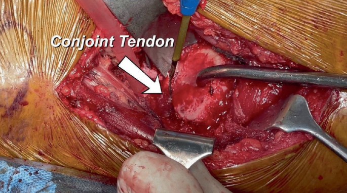
Intraoperative picture showing pulling of the bone hook with simultaneous release of the superolateral capsule from the inner surface of the GT


While performing this release, one can appreciate the proximal femur being pulled upward slowly with the bone hook.
-
3.
The remnants of the lateral neck can be removed with the rongeur. The conjoint tendon and piriformis tendons are visualized on the medial aspect of the GT. If the proximal femur is still not mobilized sufficiently, the conjoint tendon can be sharply incised with the cautery at its insertion on the medial greater trochanter. After this release, the femur should be pulled easily upward as the piriformis gets flipped posteriorly. Rarely, if the femur is still not mobilized, the piriformis tendon can be incised. Releasing these tendons improves the mobility of the femur with little morbidity as these rotators do not retract but heal in their anatomic position (Ziran and Matta 2016). Often the obturator externus tendon is visible on the medial aspect of GT at this stage. This tendon must be preserved as it has a direct medial pull on the proximal femur and provides the maximum resistance to hip dislocation. During all these releases, keeping electrocautery close to the bone is essential to avoid injury to the posterior retinacular vessels. Bleeding, if any should be coagulated properly to avoid post operative hematoma.
After all the releases are completed, a curved retractor for trochanteric elevation is placed posterior to the GT on the externally rotated femur (Fig. 7.38).

Intraoperative picture showing elevation of the proximal femur with the help of trochanteric elevator (white arrow)
The hip is then extended and adducted for femoral preparation. This can be achieved by moving the limb under the opposite limb thereby keeping it in ‘Figure-of-4’ position (Fig. 7.39).

A. Intraoperative photograph showing positioning of the operating limb under the contralateral limb. B. Intraoperative photograph showing positioning of the operating limb into a figure of ‘4’ position
Intraoperative photograph showing positioning of the operating limb under the contralateral limb.
Another curved retractor is placed against the posterior surface of the femoral neck to move it away from the acetabulum. This makes the proximal femur ready for further preparation (Fig. 7.40).

Intraoperative picture showing placement of the retractors for femoral preparation
-
11.
Femoral preparation
The femoral broaching depends on the type of femoral stem being used. The authors’ preferred stem is a short uncemented stem for which the entry point for femoral preparation will be the centre of the cut surface of femoral neck (Fig. 7.41).

Intraoperative picture showing insertion of the canal finder at the centre of the cut surface of the femoral neck for preparation of short stem
For a standard conventional stem, a canal finder is rasped into the femoral canal starting adjacent to the posterior femoral cortex and directed towards the floor for valgus positioning without penetrating the cortex (Fig. 7.42).

Intraoperative picture showing insertion of the canal finer at the posterolateral corner of the cut surface of the femoral neck for preparation of conventional stem
The rasp can be moved in and out a couple of times to ensure that it is within the intramedullary canal. After confirming the entry in the canal, successive broaching is performed till the templated size (Fig. 7.43A and B).


A. Intraoperative picture showing broaching for the femoral stem preparation. B. Intraoperative picture showing seating of the final broach
Once the appropriate broach fit is achieved, the broach is left in situ followed by insertion of trial neck and head (Fig. 7.44).

Intraoperative picture showing insertion of femoral neck and head
The hip is then reduced (Fig. 7.45A and B).

A. Intraoperative picture showing trial head being pushed with head impactor. B. Intraoperative picture showing reduction of the trial femoral component
Both the limbs are brought back into neutral position. The hip is seen under Image for the stem position. At the same time, both the limbs are assessed for Limb Length by palpating both the patellae as well as the medial malleoli (Fig. 7.46A and B).

A. Intraoperative photograph showing assessment of the limb length by palpating the patella of both sides in neutral position. B. Intraoperative photograph showing assessment of the limb length by palpating the malleoli of both sides in neutral position
Adjustment for the limb length, if any required, is done by selecting the femoral head of appropriate offset. The hip may be moved in different directions to check for the stability. Once the stability is ensured, the hip is then dislocated with the use of a bone hook around the trial neck by pulling it outward and upward while the limb is simultaneously taken into extension (Fig. 7.47).

Intraoperative picture showing insertion of the bone hook around the trail femoral neck for dislocation
The limb is repositioned into previous ‘Figure-of-4’ position and the proximal femur elevated using the trochanteric elevator. The trial implants are removed and the definite stem is then impacted with successive light blows till it seats at the calcar (Fig. 7.48A and B).


A. Intraoperative picture showing insertion of the definitive femoral stem into the prepared femoral canal. B. Intraoperative picture showing impaction of the stem. C. Intraoperative picture showing insertion of the definitive femoral head. D. Intraoperative picture showing reducing the femoral head into the acetabulum. E. Intraoperative picture showing final image after reduction
The definitive head is then placed on the trunnion and gently impacted (Fig. 7.48C).
Before the final reduction, the acetabular cup is checked and irrigated for any soft tissue interposition. The hip is then reduced by pushing the head with the help of head impactor (Fig. 7.48D and E).
A final fluoroscopic image is taken to ensure the position of the implants and check for any inadvertent complication including periprosthetic fractures (Fig. 7.49).

Intraoperative image following final reduction with definitive implants
The authors routinely do not shift the patient out of operating room without seeing the final fluoroscopic image and advocate the same to all aspiring Direct Anterior surgeons.
-
12.
Closure
The closure is performed in two layers only i.e., the anterior fascia of TFL muscle and the subcutaneous tissue with the skin. The fascia and subcutaneous tissue are closed with 2-0 vicryl (Fig. 7.50A and B) followed by staples for the skin over which a sterile dressing is applied.

A. Intraoperative picture showing closing the anterior fascia of the TFL muscle using the vicryl 2-0 suture. B. Intraoperative picture following final closure of the fascia
8.5 Pearls and Pitfalls
-
1.
The proximal femoral mobilization is the key to successful surgical outcome of DAA to hip. However, the femoral mobilization is achieved to some extent in conjunction with acetabular exposure as well.
-
2.
The acetabulum should be well exposed and the reaming should not be started unless the 360-degree view of acetabulum is available to the surgeon.
-
3.
The retractors placed should allow an easy entrance of acetabular reamer. If there is any struggle, the surgeon should revisit at the tight structures that may need further releases including the pubofemoral ligament. If the inferior capsule comes in the way of acetabular preparation, it can be excised.
-
4.
Injury to the TFL should be prevented by not retracting this muscle with excessive force. The muscle should be well protected while using the oscillating saw particularly if the neck cut has to be re-visited.
-
5.
In initial cases of learning curve, the proximal femoral mobilization can be achieved by sharply releasing the obturator internus and piriformis tendon without injuring the obturator externus.
8.6 Results and Literature Review
A multicenter prospective randomized controlled trial comparing DAA versus posterior approach in Total Hip Arthroplasty by Kevin et al. reported that DAA is a safer and effective option with better functional outcome in patients in the early post-operative period (Moerenhout et al. 2020). In a metaanalysis by Yoo et al., gait speed and hip flexion were higher in patients following DAA as compared to Anterolateral approach for THA (Yoo et al. 2019). Wang et al., in a retrospective clinical study reported that the muscle damage in DAA is less as compared to posterolateral approach which has a direct correlation with hip function after surgery (Wang et al. 2022). A systematic review and metaanalysis of DAA versus posterior approach concluded that DAA is not only associated with less blood loss and less pain scores but also cosmetically acceptable shorter incision length and early functional recovery (Wang et al. 2018).
In authors’ experience, total hip arthroplasty done by DAA as described above has shown improved outcomes when compared to our legacy posterior approach. Being a muscle sparing approach, the most important advantage has been reduced pain. This has been proven by less requirement of opioids for pain management. The patients could be mobilized early and the length of hospital stay has been almost halved which has overall reduced the cost as well (Rajesh et al. 2022). Our experience with DAA has reinforced the findings reported in the literature that it is a rational approach for THA and can be performed even without a special table. This may overcome the hesitancy among the aspiring orthopedic surgeons who have not practiced it due to the obsolete dogma of the requirement of a special table.
8.7 Summary
Direct Anterior Approach to Hip is among many other surgical approaches for performing THA. Despite a complex history of development, it has been proven that, with meticulously following the surgical key steps it can be performed with ease. The all-important technique involves the capsular releases around the acetabulum and proximal femur. Neither the reaming nor the femoral preparation should be done without adequate exposure of acetabular socket and sufficient elevation of proximal femur respectively. Femoral mobilization is considered the key step for successful outcome of DAA for THA. One should not hesitate to release the conjoint tendon and if required the piriformis as well if the femur is not sufficiently mobilized for femoral preparation. However, it is important to preserve the obturator externus to prevent postoperative instability.
References
Azim K, Kevin L, Stefan K. Predicting difficulty of femoral preparation through radiographic analysis in minimally invasive approach for total hip arthroplasty. Orthopaed Proc. 2012;94-B(SUPP_XL):89.
James CR, Peterson BE, Crim JR, Cook JL, Crist BD. The use of fluoroscopy during direct anterior hip arthroplasty: powerful or misleading? J Arthroplasty. 2018;33(6):1775–9. https://doi.org/10.1016/j.arth.2018.01.040.
Judet J, Judet H. Anterior approach in total hip arthroplasty. Presse Medicale (Paris, France: 1983). 1985;14(18):1031–33.
Learmonth ID, Young C, Rorabeck C. The operation of the century: total hip replacement. Lancet. 2007;370(9597):1508–19. https://doi.org/10.1016/S0140-6736(07)60457-7. PMID: 17964352.
Light TR, Keggi KJ. Anterior approach to hip arthroplasty. Clin Orthop Relat Res. 1980;152:255–60.
Matsuura M, Ohashi H, Okamoto Y, Inori F, Okajima Y. Elevation of the femur in THA through a direct anterior approach: cadaver and clinical studies. Clin Orthop Relat Res. 2010;468(12):3201–6. https://doi.org/10.1007/s11999-010-1349-x.
Moerenhout K, Derome P, Laflamme GY, Leduc S, Gaspard HS, Benoit B. Direct anterior versus posterior approach for total hip arthroplasty: a multicentre, prospective, randomized clinical trial. Can J Surg. 2020;63(5):E412–E417. https://doi.org/10.1503/cjs.012019
Rajesh M, Deepak G, Vivek V, Alok R, Pulak V. Two teams simultaneous bilateral total hip arthroplasty via direct anterior approach in an ordinary table—A comparative study with matched pair of consecutive bilateral total hip arthroplasty. J Am Coll Surgeons. 2022;235(5): S63–S64. https://doi.org/10.1097/01.XCS.0000896236.99384.e1
Rodriguez JA, Kamara E, Cooper HJ. Applied anatomy of the direct anterior approach for femoral mobilization. JBJS Essent Surg Tech. 2017;7(2): e18. https://doi.org/10.2106/JBJS.ST.16.00099.
Smith-Petersen MN. A new supra-articular subperiosteal approach to the hip joint. JBJS. 1917;2(8):592–5.
Smith-Petersen MN. Approach to and exposure of the hip joint for mold arthroplasty. JBJS. 1949;31(1):40–6.
Wang Z, Hou JZ, Wu CH, Zhou YJ, Gu XM, Wang HH, Feng W, Cheng YX, Sheng X, Bao HW. A systematic review and meta-analysis of direct anterior approach versus posterior approach in total hip arthroplasty. J Orthop Surg Res. 2018;13(1):229. https://doi.org/10.1186/s13018-018-0929-4.
Wang Z, Bao HW, Hou JZ, Ju B, Wu CH, Zhou YJ, Gu XM, Wang HH. The direct anterior approach versus the posterolateral approach on the outcome of total hip arthroplasty: a retrospective clinical study. Orthop Surg. 2022;14(10):2563–70. https://doi.org/10.1111/os.13444.
Yoo JI, Cha YH, Kim KJ, Kim HY, Choy WS, Hwang SC. Gait analysis after total hip arthroplasty using direct anterior approach versus anterolateral approach: a systematic review and meta-analysis. BMC Musculoskelet Disord. 2019;20(1):63. https://doi.org/10.1186/s12891-019-2450-2.
Ziran NM, Matta JM. Primary total hip arthroplasty using the Hana table. In: Bal S, Rubin LE, editors. The direct anterior approach to hip reconstruction. USA: SLACK Incorporated; 2016. p. 39–67 (Print).
Author information
Authors and Affiliations
Corresponding author
Editor information
Editors and Affiliations
Rights and permissions
Copyright information
© 2023 The Author(s), under exclusive license to Springer Nature Switzerland AG
About this chapter

Cite this chapter
Malhotra, R., Gautam, D. (2023). Direct Anterior Approach for Total Hip Arthroplasty. In: Iyer, K.M. (eds) Modified Posterior Approach to the Hip Joint. Springer, Cham. https://doi.org/10.1007/978-3-031-35790-9_8
Download citation
DOI: https://doi.org/10.1007/978-3-031-35790-9_8
Published:
Publisher Name: Springer, Cham
Print ISBN: 978-3-031-35789-3
Online ISBN: 978-3-031-35790-9
eBook Packages: MedicineMedicine (R0)