
Abstract
In this study, the energy characteristics of BEV and HEV were presented. Original experimental results for energy consumption are presented. The life cycle assessment of main types of ecological vehicles was done. As a base of comparison, the primary energy and CO2 emissions of conventional gasoline vehicle was used. An area, concerning vehicles, which are more effective in economic and ecological aspects, at average Emission factor of EU-28, is defined. For a separate country, this area will be different, depend on value of its Emission factor of electricity production. The study gives the evidences for the hypothesis that electric vehicles do not generate emissions at the place, where it runs, can be used for resolving the local problems with air pollutions, but not global.
Access provided by Autonomous University of Puebla. Download chapter PDF
Keywords
- Energy characteristics of electric and hybrid vehicles
- Life cycle assessment
- Ecological vehicles
- Emission factor
- CO2 emissions
1 Energy Characteristics of Electric and Hybrid Vehicles
1.1 Energy Consumption of an Electric Vehicle
In search of solutions for the energy crisis of the last century [1,2,3,4] and the impact of transport on global warming [5,6,7], there has been an increasing interest in the production and putting into operation of a growing number of electric vehicles [8,9,10,11,12].
The testing of the vehicle energy characteristics is possible in real road conditions or in the laboratory, on the testing benches [13, 14]. Usually the result from road and laboratory tests have some difference.
The main characteristics concerning energy properties of a BEV are energy characteristic and power characteristic. First one is relation between specific energy consumption E in kWh/km and constant speed V in km/h. the power characteristic is relation between needed power P in kW and constant speed V, km/h.
An example of energy characteristic, in case of BEV with constant gear ratio in transmission (without gear changing), is shown on Fig. 1. At the low speed, energy consumption is higher. Then, there is an interval of speeds with low energy consumption. After that, at high speeds the energy consumption increases.

Energy characteristic and distribution the total specific energy consumption of Tesla Roadster [140]
Usually the experimental result obtained on the road and in laboratory have differences. This can be seen on Fig. 2, which presents power characteristic of a converted electrical vehicle.

Fundamentals of electric vehicle energy consumption
The main purpose of energy, accumulated in the battery, is the supply electric motor and to provide electric vehicle motion in different running conditions. In addition the battery has to provide also supply of auxiliary systems, which guarantee safety travel (as lights, horn, window cleaner etc.) and comfort (as air conditioning system, media etc.). During the travel, the value of specific energy consumption (in Wh/km or kWh/100 km) can be different. Depending on the skills and desires of the driver, energy consumption can arise over 2 times more than indicated in technical specification of the electric vehicle.
In general case, the specific energy consumption can be theoretically determined by following expression
where
-
\(f_{o}\)—is the rolling resistance coefficient at low speed;
-
V—the vehicle speed, km/h;
-
G—the vehicle weight, kN;
-
kB—the coefficient of aerodynamic resistance, kN s2/m4;
-
S—the front area of the vehicle, m2;
-
\(\eta_{M}\)—the efficiency coefficient of transmission;
-
\(\eta_{E}\)—the efficiency coefficient of the electric motor and power electronics;
-
\(E_{AS}\)—the specific energy consumption of auxiliary systems, kWh/100 km.
The coefficient kB is calculated as
where
-
ρ—is the air density, kg/m3;
-
cx—the drag coefficient.
The change of the air temperature t from +40 to −20 °C cause a change of it density from 1.127 to 1.395 kg/m3 [15] and at high vehicle speed can increase the energy consumption over 10%. The value of the air density can be evaluated with good accuracy (deviation of not more than 0.5% at low temperature) using the relation
Mechanical losses in the transmission vary in wide limits and they depend on the electric motor load. The efficiency coefficient \(\eta_{M}\) with good accuracy can be evaluated using the approach, proposed in [16]. The losses in electric motor and power electronics \(\eta_{E}\) also depend on working conditions and load. The product of both coefficients vary in 90–95%, but can decrease under 50% at some running conditions [17]. It is necessary to have the characteristics of elements of electric drive, not only at nominal load (which value is given in technical specifications), but also in particular load. Some of the researchers assign these two types of losses to so-called drive train losses [18].
Distribution of the total energy consumption of electric vehicle
An analysis of distribution of total used energy can be done on the base of an existing example. On Fig. 1 a real picture of the energy consumption of the electric vehicle model Tesla Roadster at different values of the speed is presented. The Air conditioning (AC) system does not work [18].
The ratio between different parts of total specific energy consumption changes with the increase of the vehicle speed. At low speed most significant is the part of energy consumption for drive train losses and supply of the auxiliary systems. Higher energy consumption at slow motion is caused by the low values of the efficiency coefficients \(\eta_{M}\) and \(\eta_{E}\). At high speed, the part of energy, spent for air resistance becomes largest.
The energy spent for rolling resistance is changed in short limits, because of the small influence of the speed on the coefficient \(f_{o}\).
In fact, during the motion the most variable can be the parts of energy spent for air resistance and supply of auxiliary systems. The last part depends on atmosphere conditions as rain, snow, wind etc.
The curves shown on Fig. 1 are well represented by the following regression models:
-
total specific energy consumption
$$\begin{aligned} E & = 4 \times 10^{{ - 10}} V^{6} - 3 \times 10^{{ - 7}} V^{5} + 7 \times 10^{{ - 5}} V^{4} - 0.009V^{3} + 0.5715V^{2} \\ & \quad - 16.313V + 234.92,{\text{Wh/km}} \\ \end{aligned}$$(4) -
specific energy consumption for drive train losses
$$\begin{aligned} E & = 3 \times 10^{{ - 10}} V^{6} - 2 \times 10^{{ - 7}} V^{5} + 5 \times 10^{{ - 5}} V^{4} - 0.0057V^{3} + 0.358V^{2} \\ & \quad - 10.26V + 139.27,\,{\text{Wh/km}} \\ \end{aligned}$$(5) -
specific energy consumption for rolling resistance
$$E = 0.0297V + 32.278,{\text{Wh/km}}$$(6) -
specific energy consumption for air resistance
$$E = 1 \times 10^{ - 6} V^{3} + 0.007V^{2} + 0.0035V + 86.32,{\text{Wh/km}}$$(7) -
specific energy consumption for supply of auxiliary systems
$$E = 121.1V^{ - 0.794} ,{\text{Wh/km}}.$$(8)
There are many models with gearbox in the transmission. In this case the energy characteristic shows consumption at every one gear (Fig. 3). Presence of the different gears gives possibility to choose more precise the working regime of the electric motor, and to cover wider range of speeds.

Energy characteristic of a BEV on the road by gears [16]
For laboratory test, concerning energy consumption, the driving cycles can be applied [13]. There are generally accepted driving cycle ECE 15 which is for conventional vehicles and also Special cycles for electric vehicles. Results obtained under first one cycle (Fig. 4) allow to compare energy consumption of the electric end conventional vehicles [13, 18].

Energy consumption during special cycle for electric vehicles [16]
The second cycle (Fig. 5) is specially developed for electric vehicles and can be used for comparative analysis only between these types of vehicles [13].

Energy consumption during European driving cycle ЕCE-15 [16]
The energy consumption for some corporate electric vehicles [3, 13] are given in Table 1.
1.2 Fuel and Energy Consumption of a Hybrid Vehicle
One of the main environment pollution sources are vehicles [19,20,21,22,23]. In the last years, the alternative vehicle propulsion systems became the main priority for a lot of automotive companies and research teams. The basic objective of those propulsions [20, 24,25,26,27] is the achievement of energy independence from nonrenewable sources like liquid and gas fuels. One of the variants of vehicle propulsion, which is built-in a few vehicle models is hybrid system [25, 28, 29].
According to the information from the producers and a number of studies [21, 24, 25, 29,30,31,32,33] hybrid vehicle consumes less fuel and generates les air pollutions in comparison with a vehicle equipped with a gasoline or diesel engine during the city motion. Similar effect exists for inter-city conditions. That is one of the main advantages of hybrid vehicles because in city conditions, up to 50 km/h, the motion is realized using only electric energy from the battery.
In some studies [24,25,26, 28,29,30, 34] there are verifications that hybrid vehicle has advantages versus gasoline, even versus diesel vehicle especially in urban conditions. The fuel consumption in inter-city conditions are not well studied.
Estimate the energy or fuel consumption of a hybrid vehicle is very complex problem, because of computer control system and properties of transmission (CVT or not).
Fuel consumption at constant speed and energy characteristic of an example—Toyota Yaris Hybrid 1.5 HSD is presented on Fig. 6. At low constant speed, the energy consumption is a little higher (Fig. 6), which is a result of low values of the transmission and electric propulsion efficiency. Then the energy consumption slowly goes down. Up to 50 km/h fuel consumption is zero l/100 km, because for the motion, the vehicle use only electric energy (approximately 0.08–0.1 kWh/km) from the battery. At constant speed over 50 km/h, the fuel consumption is practically equal to that one of the conventional variant of the same vehicle. At high-speed conditions, the hybrid vehicle runs using only ICE. Obviously, it is not appropriate to make comparative analysis of different models hybrid vehicles only on the base of fuel consumption and energy characteristics. In real traffic, usage of the electric or ICE mode depends on many factors, including not only road conditions, speed, traffic density but also driver’s skills, discharge level of the battery etc.

Fuel consumption and energy characteristic of Toyota Yaris Hybrid 1.5 HSD [25]
Our opinion is—an additional study of the fuel consumption of hybrid vehicle in urban and inter-city conditions is needed. That way a full picture concerning fuel and energy properties of the tested vehicle can be obtained.
Study of the fuel consumption of the hybrid vehicle in urban conditions
The experiments include series of tests in urban routs in Bulgarian town Ruse. Consumption on three typical urban routs [35] were investigated:
-
Route 1 “Rail station—Danube bridge—Rail station” (Fig. 7);
Fig. 7 
Route 1 “Rail station—Danube bridge—Rail station”
-
Route 2 “Rail station—River station—Rail station” (Fig. 8);
Fig. 8 
Route 2 “Rail station—River station—Rail station”
-
Route 3 “Rail station—Druzhba 3—Rail station” (Fig. 9).
Fig. 9 
Route 3 “Rail station—Druzhba 3—Rail station”


The first route has a predominant plane terrain and a distance of 15.3 km. The second one includes horizontal and also parts with longitudinal inclination. On this route the motion in one direction and return to start point are realized by passing through different streets, because of presence of one way streets. Distance of the second route is 4.6 km. The third route has a predominant hill terrain. The distance is 6.4 km.
Motion was realized in the traffic peak period—17–18 h. Every route was passed in two modes—without and with activated “ECO MODE” of the hybrid system. The load of the vehicle was 3 persons (including driver). During the all experiments the AC system was working.
The choice of the routes was realized taking into account the fact that all are with intensive traffic, different traffic regulation and include parts with different inclinations. Before series of road experiments, a verification of the fuel consumption, indicated by the vehicle board computer was done using Flowtronic 205. The difference between board computer and Flowtronic 205 result for the average fuel consumption, passing a distance of 2 km, at different speeds is less than 2%.
Every experiment was repeated 3 times. At the end of the experiments, in the laboratory, the results were proceeded and the graphics were created [23]. All results in urban conditions are summarized in Table 2.
The average fuel consumption of the hybrid vehicle Toyota Yaris is significantly higher from that one indicated from the producer in the technical specification (see Table 2). Possible reason for that difference can be explained with the density of the real traffic in Ruse at peak period and European city cycle. It is obvious that fuel consumption of the HEV on all three routes without “ECO MODE” is higher than that the one with working “ECO MODE”. Using “ECO MODE” the vehicle accelerates slowly.
The fuel consumption on the first route without and with working “ECO MODE” is respectively 61.3% and 35.4% higher than indicated in technical specification of the producer. The fuel consumption on the second route without and with working “ECO MODE” is respectively 119.4% and 64.5% higher than indicated in technical specification of the producer. The fuel consumption on the third route without and with working “ECO MODE” is respectively 87.1% and 74.2% higher than indicated in technical specification of the producer.
In urban conditions, the energy saved in the battery and regeneration of the energy during braking are used more active. The less using of the ICE decreases the fuel consumption and energy performance of the hybrid vehicle is similar to that one of the less powerful conventional model Toyota Yaris (P3)—1.0 VVT-i 5 M/T (Table 4).
Study of the fuel consumption of the hybrid vehicle in inter-city conditions
Fuel consumption on three inter-city routs were investigated:
-
Route 1 “Ruse—Varna—resort Golden sands—Ruse” (Fig. 10);
Fig. 10 
Inter-city route 1 “Ruse—Varna—resort Golden sands—Ruse”
-
Route 2 “Ruse—Sozopol—Ruse” (Fig. 11);
Fig. 11 
Inter-city route 2 “Ruse—Sozopol—Ruse”
-
Route 3 “Ruse—Silistra—Ruse” (Fig. 12).
Fig. 12 
Inter-city route 3 “Ruse—Silistra—Ruse”


The choice of the routes was made taking into account combination of the inter-town, high way and urban parts. The combination of the uphill, downhill and horizontal part in the routes is also considered.
Route 1 “Ruse—Varna—resort Golden sands” and return (Fig. 10) includes motion on the first class road Ruse—Shumen, on the high way Shumen—Varna and in urban conditions. Route 2 “Ruse—Sozopol—Ruse” (Fig. 11) has a specific relief (motion uphill, downhill and horizontal parts). The route distance is 300 km. The experiment is done with 2 passengers and working AC system. Route 3 “Ruse—Silistra—Ruse” (Fig. 12) is 116.9 km. The experiment is done with working AC system. The load was 4 passengers in direction Ruse—Silistra and 3 passengers in direction Silistra—Ruse. The route is plane and different number of passengers give the possibility to estimate the influence of the vehicle load on the fuel consumption. During the pass of the routes, the “ECO MODE” was deactivated for all 3 routes. The results for current and average fuel consumption of the hybrid vehicle are presented in Table 3.
Route 1 “Ruse—Varna—resort Golden sands—Ruse”. The obtained results show that average fuel consumption of the whole route is significantly higher than indicated in technical specification of the producer (see Tables 3 and 4). The difference is up to 40–50%. The cause probably is different motion intensity out of the towns and on the high way, in comparison with used European cycle using by the producer to estimate fuel consumption of the hybrid vehicle. Less using the ICE decreases the fuel consumption of the hybrid vehicle in urban condition and this way decrease the consumption for whole route. In inter-city conditions, the fuel consumption is similar to this one of the conventional vehicle of the same producer (5.4 l/100 km for combined cycle of motion). In this case, the effect of the hybrid system is minimal.
Route 2 “Ruse—Sozopol—Ruse”. Differences of the fuel consumption in separated parts of the route, in two directions are minimal. Exception is this part, which concerns exit and entrance in Ruse because of uphill and downhill motion in different directions of the route. One can see on the figures part with zero consumption. They correspond to passes through small villages, with limited speed less than 50 km/h. During those periods hybrid vehicle was moving on the electric energy only thanks to full charged battery in inter-city conditions. The fuel consumption of the hybrid vehicle on the route is significantly higher than indicated in technical specification of the producer (see Tables 3 and 4).
Route 3 “Ruse—Silistra—Ruse”. In inter-city conditions, the fuel consumption is similar to that one of the conventional vehicles of the same producer and the effect of the hybrid system is minimal. Less consumption is registered during the exit of Silistra and during the entrance in Ruse, because of the downhill motion. The difference of 1 person less into return direction causes a less fuel consumption of 0.65 l/100 km.
A complex study of the fuel consumption of a hybrid vehicle Toyota Yaris was done. Original data for motion at different constant speeds were obtained. The economical and energy characteristics of the vehicle was received and analyzed. At low constant speed, the energy consumption is a little higher (Fig. 3), which is a result of low values of the transmission and electric propulsion efficiency. Then the energy consumption slowly goes down. Up to 50 km/h fuel consumption is zero l/100 km, because for the motion, the vehicle use only electric energy (approximately 0.08–0.1 kWh/km) from the battery. At constant speed over 50 km/h, the fuel consumption is practically equal to that one of the conventional variant of the same vehicle. At high-speed conditions, the hybrid vehicle runs using only ICE. It is not appropriate to make comparative analysis of different models hybrid vehicles only on the base of fuel consumption and energy characteristics.
The fuel consumption at urban routes is different for the separated routes (Table 2 and Fig. 7). Probably the differences are generated by the terrain, the traffic and battery recharge. In real urban conditions, at rush hours, the hybrid vehicle has significantly higher consumption than indicated in technical specification of the producer—for studied routes from 61.3 to 119.4%. The usage the “ECO MODE”, in urban conditions, reduce the fuel consumption with 7.4–33% for separate routes and average for all routes consists 20%. Improving the fuel consumption is connected with worse dynamic performance.
In the real inter-city conditions, the motion of the hybrid vehicle is essentially realized by the ICE. The investigated vehicle has a 31.4–48% higher fuel consumption than indicated in technical specification of the producer. Usage of the “ECO MODE” in inter-city conditions has no significant effect. The minimal effect (under 4%) is a result of motion in villages with limited speed, basically on the electric energy.
The effect of the hybrid driving system is contradictory. In urban conditions, hybrid system has up to 31.3% less fuel consumption (with “ECO MODE”) in comparison with an equivalent conventional model. In Inter-city conditions, the fuel consumption is practically equal to this on of the conventional vehicle Toyota Yaris (P3)—1.0 VVT-i 5 M/T. The effect on the consumption in urban conditions depending on intensity of the motion, road profile, possibility for regeneration, “green wave” etc.
The opinion of the research team is that have to be built-in battery with higher capacity. This action will improve effect of the hybrid system. The existing battery of 0.94 kWh assures a motion of 3 km on horizontal terrain, which is not enough in an urban route of a middle-size East European town.
1.3 Energy Consumption of Electric Bicycle
Moving in urban areas is connected with big intensity, often braking and starting and continuous working of the engines in idle mode. The increased fuel consumption leads to increased level of the air pollutions.
The governments in the different countries apply different measures for stimulation the use of environmentally cleaner vehicles [19, 36,37,38,39] and production of electric energy by renewable energy sources [19, 38, 40].
Many European and Asian countries encourage the usage of bicycles and special attention is paid to the bicycle moving infrastructure [38, 39, 41]. One special category of the vehicles is the electric bicycles. They combine some advantages both from the classic bicycle and the electromobile [19] such as less costs for self-movement, typical for the two-wheeled vehicles, possibility for electric operation or help for climbing etc. In the bigger part of the existing ones there is a possibility provided for generating of energy by charging of the battery during braking or descending.
It is well known that the bicycle has a very low energy consumption in comparison of BEV. For the purposes of the research, a team from the Ruse University has worked out an experimental electric bicycle [42] based on a Bulgarian bicycle and electric elements. The general structure of the electric bicycle is shown on Fig. 13.

General view of the electric bicycle: 1—frame; 2—back wheel with a chain mechanism; 3—battery; 4—controller; 5—electric motor; 6—handlebar
The electric bicycle is operated by BLDC electric motor 5 with a nominal power of 500 W, built-in the front wheel. It is operated by lithium ion battery 3. The battery has a working tension of 36 V, capacity 9 Ah and a mass of 3.5 kg. The battery contains 324 Wh electric energy. The total mass of the electric bicycle is 24.4 kg.
The parts for operating and control are assembled on the handlebar. The controller optimizes the working regimes of the electric motor and the regime of regenerative braking. The autopilot provides a constant speed of the electric bicycle thus giving a possibility to free the right hand from the speed regulation lever. The regenerative stopping is operated by a separate button aiming to eliminate the eventual switch on of the mechanical brake system.
The energy consumption of the electric bicycle has been studied during different working regimes. There have been made experiments on a horizontal road in two directions with a five time repeating at constant speeds from 5 to 30 km/h. The total weight of the electric bicycle and the cyclist was 99.4 kg. The power P from the electric motor at different speed V of the electric bicycle is shown at Fig. 14. The energy characteristic—energy consumption E per 1 km at different constant speeds V is shown at Fig. 15.

Dependence of the used motor power P by the speed V

Dependence of the energy consumption E by the speed V
Study on the regenerative braking of the electric bicycle
At serial production the electric bicycles and the sets on the market, the regenerating braking is achieved by the levers for activation the front and the back brake. At the first starting of the lever only the regenerating braking is switched on and after that depending on the power of pressing of the lever is achieved the desired brake delay, accordingly from the two braking systems—the electric and the mechanical.
At present, there are no enough researches for the effectiveness of the regenerative braking of the electric bicycles in urban areas. In [43] it is indicated that depending on the conditions of moving and the slopes of the streets, the regeneration of energy varies from 6 to 14%. The experiments made in city of Ruse during a covered distance of 215 km at some of the routes of the public transport a regeneration of 5.5% is obtained.
The full stop only by electric motor, without using the mechanical brake is impossible. At the beginning there is only regenerating braking and after that it is necessary to switch on some of the braking systems to be achieved a full braking.
There have been made experiments at different initial speed and only regenerative braking has been performed. The results from the studies are presented at Fig. 16. Each full braking or speed reduction through the electric motor increases the run of the electric bicycle and the exploitation time of the mechanical brake system.

Dependence of the regenerating capacity in the battery Creg versus initial speed of braking Vs
It is possible in the infrastructure of the urban area to be realized descending with a speed reduction possibility through the electric motor. With this regard there have been performed experiments of descending at different speed. The results from the experiments are shown at Fig. 17. At the different values of constant speed V is reported the regenerated current Ireg which charges the electric battery.

Dependence of the regenerative current Ireg versus speed of the electric bicycle V
From this characteristics it is seen that upon descending with speed 25 km/h in a regenerating regime for 60 s (the slope is 420 m long) in the battery will be regenerated ~0.17 Ah. At 9 Ah battery capacity, this regenerated capacity is ~2%.
Study the energy consumption for typical routes in the conditions of a medium size town
For the study of the energy efficiency of the electric bicycle there have been chosen three typical routes in the town of Ruse (population ~150,000) with a different profile but with a heavy traffic. They are shown at Figs. 7, 8 and 9. For their visualization a virtual map has been used.
The three routes were passed by two group experiments. Firstly, at the beginning without the help of the cyclist and starting only by using the electric motor for acceleration. Again, the same routes have been passed with the help of the cyclist though the bicycle pedals only at staring until reaching a speed of 5 km/h. All the experiments have been started with fully charged battery. The results are shown at Table 5.
There has been made an experiment also for determination the operating range of the bicycle at a daytime period with a less traffic (Sunday morning). The average results from route 1 showed that with one charge of the battery, the electric bicycle passes a distance of 34.77 km in urban conditions, without using the regenerative braking. The maximum achieved speed was 35.4 km/h and the average speed—23.8 km/h. For the whole pass of the route, the electric bicycle has used 390.49 Wh of energy and average per km—11.2 Wh/km.
From the carried-out research and the analyses of the results, the following conclusions could be made:
Without regeneration of the energy in urban conditions the range of the electric bicycle is about 35 km. Considering the average value of the regenerating energy in a town of Ruse, the run of the electric bicycle could be increased from 5 to 10%. At daytime periods with not so heavy traffic, the run of the electric bicycle could be increased with about 11% due to the smaller number of braking and accelerations.
The studies showed that in a town like Ruse, the use of electric bicycle instead of other vehicles by one person could reduce the air pollutions up to 10 and 15 times compared to the electromobiles and the conventional vehicles.
At speed of 15–25 km/h the used power of the electric motor is from 100 to 300 W and the energy consumption is from 7 to 12 Wh/km which is 6–23 times less than the energy consumption of the electromobiles produced now. There is a bigger effect from the regeneration of energy at the routes including slopes. For example, at the plain route 1 the regeneration is about 5%, but at routes 2 and 3 including slopes the regeneration reaches about 10%.
The level of increasing the effectiveness of the regenerative braking depends on the road infrastructure for moving of bicycles and electric bicycles, and the chosen by the cyclist regimes for speed reduction and braking.
1.4 Energy Consumption of the Auxiliary Systems of Electric Vehicles
An important characteristic of energy performance of the electric vehicle is traveled distance for one charge of battery [16, 18, 44]. Usually, in the technical specification of electric vehicles, the producers give an operational range, which is not precisely detailed concerning the conditions of motion (in city or inter-city traffic, what is the air temperature, what use of the auxiliary systems etc.). For the owners it is very important to know as realistic as possible the remaining travel distance and influence of auxiliary systems on energy consumption and distance [45,46,47,48]. That knowledge will ensure a calm and comfortable travel, independent of limited energy autonomy of electric vehicles. The goal of the study is to analyze the influence of different auxiliary systems of electric vehicles on the travel distance at different running conditions and comfort (as temperature in the vehicle, using the lights, audio system etc.).
A significant influence on the energy consumption have auxiliary systems—the second part \(E_{AS}\) of relation (1). The approach for their assessment has to be very accurate, especially when the maximal power of those devices is in use, to assure exact determination of travel distance.
The power supply of auxiliary systems is realized by the second (operational) battery at voltage of 12 V. It can be recharged from the traction battery trough DC/DC convertor. The losses during this transformation have to be taken into account by introducing a coefficient marked as \(\eta_{DC}\). Finally, the specific consumption of the auxiliary systems can be represented as
where
-
\(\eta_{DC}\)—is the efficiency coefficient of the convertor between two batteries;
-
\(E_{CC}\)—the specific energy consumption of AC system;
-
\(E_{L}\)—the specific energy consumption of lights and horn;
-
\(E_{WCS}\)—the specific energy consumption of windows cleaning system;
-
\(E_{OS}\)—the specific energy consumption of other systems as SRS, ABS, TC ESP, electric windows open system etc.
Energy consumption of the separate auxiliary systems
Approximately, the energy consumption of the auxiliary systems presented as % of energy charged in the main (traction) battery is shown in Table 6 [45, 46].
The presented information in Table 6 is more general and does not include all operational conditions of electric vehicles. This is a reason to make a review, concerning influence of different factors on energy consumption of each auxiliary system.
AC system
The normal internal temperature of the air in the compartment have to be 20–23 °C. To maintain that limits, the energy consumption of AC system depends on temperature difference in and out of the vehicle. Table 7 presents an example concerning needed power of control system at different internal temperatures and high external temperature [45].
The maximal value of the power supply of AC system can achieve 3–5 kW for some vehicle models. As heat device they use electric heater or heat pump.
On Fig. 18 the influence of power consumption of 2 kW (working AC system) on travel distance is illustrated for electric vehicle Tesla Roadster [18].

Influence of AC system power consumption of 2 kW on the traveled distance per one charge of battery for electric vehicle Tesla Roadster [140]
At speed of 25 km/h, the travel distance per one charge of the battery decreases approximately 2 times when the AC system of 2 kW works. The curves are well represented by the following regression models:
-
travel distance without working AC system
$$\begin{aligned} L & = - 9 \times 10^{{ - 10}} V^{6} + 6 \times 10^{{ - 7}} V^{5} - 0.0002V^{4} + 0.0228V^{3} - 1.6088V^{2} \\ & \quad + 50.131V + 116.1,{\text{km}}. \\ \end{aligned}$$(10) -
travel distance with working AC system of 2 kW power
$$L = 4 \times 10^{ - 6} V^{4} + 0.0018V^{3} - 0.3157V^{2} + 19.881V + 10.837,{\text{km}}.$$(11)
There are not many researches concerning influence of the external air temperature on the energy consumption. In [49] a Canadian company, on the base of over 7000 travels in the whole North America, have made a generalization of average energy consumption of electric vehicle Nissan Leaf (Fig. 19).

Influence of the external air temperature on the specific energy consumption of electric vehicle Nissan Leaf [140]
The curve from Fig. 19 is well represented by the regression model
The same data is shown on Fig. 20 as influence on the travel distance L [50]. The respective regression model is

Influence of the external air temperature on the range of electric vehicle Nissan Leaf [140]
It is obvious that external air temperature has a significant influence on the energy consumption of electric vehicle. The explanation is connected with energy for heating or cooling but also with efficiency of battery at different temperatures. Taking into account these two factors, one can see an optimal external air temperature at which the energy consumption is minimal and travel distance is maximal (Figs. 19 and 20). This optimal value is approximately 20 °C.
Light system, light signalization and horn
The energy consumption of the light system and signalization depend on twenty-four-hour period—if the travel is realized in the day or in the night. That is especially important for long and short front lights. Usage of elements of light system and signalization, during 100 km travel, are presented in Table 8. The data from different sources [47, 48] was proceeded and a generalization was done.
The calculations show that maximal energy consumption of light system using conventional lamps at night travel is about 150 Wh/100 km. Usage of the LED-lamps decrease the consumption 2.2–3.8 times [44, 47, 48, 51, 52].
In specialized literature there is no information concerning time for use and energy consumption of the horn. Probably, because the value of used energy is insignificant.
Audio system
Energy consumption depends on the power characteristic and time for use of the system. Usually built in systems have a power supply of about 200 W. The time for use of the audio system vary in wide limits and correspond to driver and passenger’s needs.
Actual energy consumption also depends on sound level. Some authors [17], in simulation models, give an average power supply of 20 W for audio system and use ratio approximately 75% of travel time.
Windows cleaning system and seat heating
This system uses electric motors with maximal power of 30–50 W. Time of use strongly depends on the weather (if there is the rain or snow).
The average consumption of the seat heating system is 30 W and mean use ratio—5% of time [17].
Other systems
The main included in this group are: system of passive safety—SRS; Anti-lock Braking System—ABS; Traction Control System—TC; Dynamic Stability System—ESP; systems for opening and closing of door windows and roof. The biggest consummators form this group are the systems for active safety, but value of energy depends on driving style.
Internal losses in traction battery
Depending on the battery type, during idle time (no traction) the additional losses can present for maintenance of the working temperature. For example, some metal-hydride batteries work at a temperature of approximately 300 °C and permanent consummation power of 60–80 W for temperature maintenance. If the capacity of the battery is 18 kWh after 10 days idle time it will be fully discharged.
Internal losses of the Lithium-ion batteries depend on the number of the connected cells and Battery Management System—BMS.
Every battery has a limited period of exploitation. To extend that period the power electronics controls charge/discharge process. This means that only a part of the battery capacity can be used—full charge and discharge are unavailable. This is made to provide the possibility for accumulation of the regenerative braking energy.
Influence of the regeneration on the travel distance
Regeneration of electric energy is possible during braking process. Depending on running conditions and route characteristic, the maximal value of regenerative energy vary from 10 to 25% in city conditions [53, 54]. The experimental results [53, 54] show that braking deceleration in limits 2–3 m/s2 can assure efficiency of regenerative braking up to 90% and minimal transformation of kinetic energy to heat and friction in mechanical braking system (Fig. 21).

At bigger decelerations, the battery cannot receive regenerative energy, the mechanical braking system is switched on and all two system work together to provide required deceleration (Fig. 22).

To improve usage of regenerative energy they often build in traction system supercapacitors (especially in buses).
On the basis of investigation and analysis of influence of the running conditions and auxiliary systems on the energy consumption of an electric vehicle, the following conclusions can be formulated. The minimal energy consumption of electric vehicles is realized at lower speed—up to 40 km/h. These values are significantly lower than respective for conventional vehicles—approximately 65 km/h.
At low speed, for example 5 km/h (hard traffic and jams), the energy consumption can be equal to that one at 100 km/h. The cause for this is low efficiency of the drive train and big part of energy consumption for supply of the auxiliary systems at low speed motion. At high speed—over 50 km/h, the influence of the part of auxiliary systems in total energy consumption decrease and the energy consumption spend for air resistance becomes dominant.
At some values of speed and weather conditions, the energy consumption for the supply of auxiliary systems can decrease twice travel distance of the vehicle.
The minimal energy consumption of auxiliary systems is realized at external air temperature of 20 °C, at which the biggest travel distance is achieved.
The light system and signalization consume about 1% of total energy consumption of electric vehicle.
It is very important to indicate that all above regarded characteristics do not present exactly total spent energy and generated emissions during whole “LIFE” of the vehicle. It is obviously that one other assessment has to be applied.
2 Life Cycle Assessment of Vehicles, Using Different Types of Fuels or Electricity. Energy Consumption and CO2 Emissions
During the last decade, the Life cycle assessment (LCA) became a dominant methodology into researches concerning sustainable development of a product [55]. LCA is applicable also for study influence of a production process on the environment. Existing researches [56,57,58,59,60,61] about the effectiveness of fuel production and use in vehicles stimulate environment protection and support development in this area.
Building of a sustainable transport system is connected with modernization of existing vehicle park using ecological vehicles. The alternative vehicles can be classified as:
-
Gasoline fuel vehicles (GV);
-
Flexible fuel vehicles (FFV);
-
Dedicated vehicles (DV);
-
Bi-fuel vehicles (BFV);
-
Dual fuel vehicles (DFV);
-
Battery electric vehicles (BEV);
-
Hybrid electric vehicles (HEV);
-
Hydrogen fuel-cell vehicles (FCV);
-
Compressed-air vehicles (CAV).
In this study, the following values of the quantities and assumptions are used:
-
equal mass of the all types of vehicles;
-
energy consumption of the BEV—0.210 kWh/km;
-
fuel consumption of the GV—7.6 l/100 km of gasoline;
-
capacity of the battery of BEV—40 kWh;
-
equal range of the life cycle all types of vehicles—290,000 km;
-
energy for vehicle production—11,900 kWh [59];
-
efficiency of NPS—29.5% [62];
-
efficiency of TPS using coal—26% [63];
-
efficiency of TPS using natural gas—40% [64];
-
efficiency of water power station (WPS)—60% [65];
-
efficiency of wind power station (WiPS)—40%;
-
average efficiency of power stations using renewable energy sources—50%;
-
losses for transport and distribution of the electricity—5% [66];
-
efficiency of gasoline fuel production—89.1% [67];
-
efficiency of liquid petroleum gas (LPG) fuel production—94% [67];
-
efficiency of natural gas (NG) fuel production—91% [67];
-
losses due to leakage of NG—1.5% [68];
-
losses due to transformation of NG in liquid phase—8% [69];
-
generated CO2 emissions during burning process of: gasoline—240.82 g/kWh; NG—183.96 g/kWh; LPG—214.48 g/kWh [60];
-
global warming potential (GWP) of NG—25 [66];
-
emission factors of electricity production for Bulgaria, Poland, Norway and average for EU-28 are respectively—669,980, 17 и 447 g/kWh [59, 70];
-
in LSA of different types of vehicles, used primary energy and generated emissions due to fuel transportation are not included. Their values can be different for each country. This way a more precise analysis of advantages and disadvantages of separate type of vehicles can be done.
2.1 Life Cycle Assessment of Electric and Conventional Vehicles
In view of decreasing the impact of vehicles on global warming in recent years, more and more electric vehicles replace the conventional ones. Following this trend, a lot of companies direct their efforts at producing vehicles with electric propulsion using Li-ion battery. An electric vehicle at appropriate running conditions can be more effective than the conventional one in terms of environment safety. The general structure of an electric vehicle is presented on Fig. 23. This kind of vehicles use the electric energy accumulated in the traction battery, which supplies the electric motor. Different kinds of batteries (Li-ion, LiFePO4 etc.) and electric motors (PMDC, BLDC, AC etc.) exist.

Structure of an electric vehicle: 1—cooling system; 2—DC/DC convertor; 3—power electronics; 4—electric motor; 5—traction battery; 6—charging contact; 7—transmission; 8—charging device; 9—operational battery [74]
There are studies [68, 71,72,73,74] of the effectiveness of electric vehicle versus conventional ones in terms of emissions of greenhouse gases adjusted to carbon dioxide equivalent (CO2). Usually, this type of studies is done using the Life Cycle Assessment (LCA) method [55] and the comparison is made for the energy consumption and/or CO2 emissions. LCA is used to assess the environmental impact during all stages of vehicle life including extraction of raw materials and energy source, materials processing, vehicle manufacture, distribution (transport), use (motion) including maintenance and repair, and finally recycling or disposal [55]. The interest of researchers [66, 68, 71,72,73, 75,76,77,78,79], and our interest is focused mainly on the results for energy consumption and CO2 emissions, obtained through LCA.
In [71] different models of vehicles are studied. The main conclusion is that all the BEVs researched have lower CO2 emissions than ICE vehicles when the electricity comes from the European mix. The well-to-wheel CO2 emissions are reduced by approximately 50% as compared to a similar internal combustion engine vehicle. It is not clear what is the energy spent for battery production.
Study [68] calculates the energy inputs and CO2 equivalent emissions of a conventional gasoline vehicle, a hybrid vehicle, and a battery electric vehicle. The aim is to determine the lifecycle environmental costs of each vehicle type in conditions of California. The main purpose of the study is to examine the environmental impact of each vehicle type, taking into account lifecycle energy usage and both CO2 equivalents and air pollution emitted. The models are developed and the impact of a variety of factors, including carbon intensity of gasoline and electricity, varied electricity mixes, battery lifetime, and fuel economy is studied. The cost effectiveness for each vehicle type was also calculated.
Study [72] models the relative impact of new BEVs and ICEVs in the US for the year 2015, and it projects the economic and environmental impact of BEVs and ICEVs over the entire assumed twenty-year lifetime of a US passenger vehicle.
A lot of sources [18, 75, 77, 78, 80,81,82,83,84] contain particular data about the elements and processes included in LCA of vehicles, but some of them are fragmentary and contradictory, which does not permit appropriate use for comparative analysis. The results from the above-mentioned studies show that the average electric energy mix of the respective country has the main impact on CO2 emissions. A full comparative analysis, based on the LCA method and concerning used energy and generated CO2 emissions of electric and conventional vehicles in Bulgaria does not exist. The present study is concerned with that problem. LCA of electric and conventional vehicles, based on data about the electric energy mix in some specific EU countries (like Norway, Poland and Bulgaria) and in EU-28, is made.
The generated emissions in CO2 equivalent for production of 1 kWh electric energy depend on the electric energy mix for the respective country. In Europe, the larger part of electricity is produced by thermal power stations using coal (TPS), nuclear power stations (NPS) and stations using renewable energy sources (RES). In some countries like Holland, the main part of the electricity is produced using natural gas (NG).
In Table 9 the electric energy mix for European counties (EU-28) is presented [65, 80, 83]. In the last row, similar information about Norway is given [80, 83]. In some of the countries, the total percentage is not a full 100% because of using small local electric generators, which is not significant for the statistics.
During the production process, power stations’ direct and indirect emissions are generated. The volume of that emission depends on the life cycle of the power station. For example, production of electricity from NPS and from RES has no direct emissions and this is the reason to use electricity produced in such stations for charging electric vehicles.
The summarized information for the countries of EU-28 concerning the emissions of CO2 generated for the production of 1 kWh electric energy is given in Table 10 [66, 83, 85]. The whole life cycle of the used primary energy source is taken into account. In different countries, even with the same type of primary energy source, the volume of emissions may not be equal. Many factors influence these emissions (like needed energy for production and transport of the fuel, using the innovative technologies in production process etc.), but they will not be analyzed in this study. For a correct LCE of the electric and conventional vehicles all spent energy, including energy for production the primary energy source, for vehicle and battery production, for using the vehicle and finally for utilizing the old components, have to be considered.
The fuel consumption of the GV is determined based on the specific energy and efficiency of its internal combustion engine, and with the assumption to have the same volume of energy as that one used for motion of the BEV [68]. In the values of efficiency of different power stations, the losses for extraction of the primary energy sources (coal, natural gas etc.) are taken into account.
The performance of the BEV basically depends on the type of traction battery. The production technology of Lithium-ion battery for electric vehicles is not so cheap in comparison with traditional lead-acid battery.
The energy spent for the production, transport, recycling etc. of the most popular types of battery was calculated on the basis of data from [75] and is shown in Fig. 24. Our study about battery recycling confirms the popular opinion that this process is not economically effective because of high energy consumption and waste products presence. Probably in the future battery recycling will be oriented basically for ecological effect and observance of ecological law.

Energy spent for production and recycling per 1 kWh of capacity of the different battery types [74]
The results show that the life cycle of Li-ion battery needs about 420 kWh per each kWh of battery capacity. For a middle size battery of 40 kWh capacity, approximately 16,800 kWh energy will be used during the life cycle of the BEV, if only one battery is used during the life cycle of BEV (range of 290,000 km). The battery construction permits repair and change of elements. According to some authors [68] it is reasonable to make calculation for 1.5 batteries. In this case, the energy for the life cycle of battery will be one and half times more.
Taking into account the values of the energy spent for vehicle production, battery life cycle and energy or fuel for passing a distance of 290,000 km, the needed energy for the life cycle of BEV or GV can be calculated.
The obtained results for primary energy used in the life cycle of BEV, produced and driven in 4 countries, are presented in Fig. 25a. The energy mix and efficiency of the power station for different countries are used in the calculations.

Life cycle of primary energy (a) and СО2 emission (b). BEV-1—production and driving in Bulgaria; BEV-2—production and driving with data for EU-28; BEV-3—production and driving in Norway; BEV-4—production and driving in Poland
Generally, the life cycle of the gasoline GV, produced and driven in Bulgaria, needs approximately 309,750 kWh of primary energy. About 86.5% of the life cycle energy is spent on motion. This percentage depends on the energy for vehicle production in the respective country and the last one depends on the energy mix. The energy for motion/ driving changes insignificantly in different countries and basically depends on the losses in the fuel production process. Other stages of the life cycle of GV like production of vehicle and parts, their transportation etc. consume less energy—13.5% of life cycle energy or approximately 42,000 kWh.
The fuel consumption of the vehicle is determined on the basis of fuel calorific value and efficiency of the gasoline engine so that a match with energy used by the electric vehicle presents [68]. Accepted values of power plants efficiency take into account also the losses in the production of respective fuels.
The results obtained for the primary energy consumed for the life cycle of the BEV and the GV are shown in Fig. 25a [74]. The results represent 4 typical examples—3 countries and EU, which have very different energy mixes.
Overall, the GV for life cycle (production, transport, exploitation, recycling and disposal of waste), needs approximately 309,750 kWh of primary energy, while the BEV-1, including the traction battery needs 355,210 kWh. Obviously, the life cycle of BEV-1 requires approximately 15% more primary energy than GV produced and operated in Bulgaria (Fig. 25).
For the GV vehicle, approximately 86.5% of the life cycle energy is spent during exploitation. This percentage for the different countries will depend mainly on the energy spent for manufacturing the vehicle, which depends on the country’s energy mix. The energy needed to operate the vehicle for the different countries changes insignificantly and will depend mainly on the losses in fuel production. Other life cycle stages, such as vehicle production and spare parts, waste transportation and disposal, require much less energy—13.5% of the total life cycle energy or approximately 42,000 kWh.
In the case of an electric vehicle, the most energy is used for charging the battery—71.5% of the total life cycle energy. Battery production also has a significant impact—16.7% of total energy for the life cycle or 59,290 kWh. The energy at the stages of production of electric vehicle and spare parts, transportation and disposal of waste is approximately 11.8% of the total energy or 42,000 kWh (as much as the GV vehicle).
For the BEV-2 produced and operated with the EU-28 average mix (Table 10), the primary life cycle energy requirement is approximately 16% lower than the BEV-1.
The most energy efficient is the BEV-3—produced and operated in Norway. Primary energy is approximately twice less (49%) than BEV-1. In this case, the BEV-3 will save more than 42% of the primary energy compared to the GV produced in Bulgaria, and 38% lower than GV produced in Norway.
The most inefficient in terms of primary energy consumption is the BEV-4 produced and operated in Poland—about 51% more energy than that the BEV-3.
The generated CO2 emissions for the life cycle of above-mentioned vehicles are shown in Fig. 25b. The BEV-1 has 59,940 kg of CO2 emissions. It is almost as good as the petrol vehicle GV—59,750 kg. However, the advantage has to be given to an electric vehicle, because it doesn’t generate harmful emissions where operates—the emissions are emitted where the electricity is produced.
The electric vehicle BEV-2 has lower emissions (40,050 kg) compared to BEV-1 by 31%. The minimal value of the CO2 emissions has life cycle of the BEV-3—1530 kg, or 39 times less than BEV-1 (as much as GV), 26 times less than BEV-2 and nearly 59 times less than BEV-4. Compared to a GV produced in the same country, CO2 emissions of BEV-3 are approximately 34 times less (due to lower emissions at the vehicle production stage).
BEV-4 has the highest level of energy consumption and generated emissions. It is produced and driven in Poland, where 78.6% of the electricity is from thermal power stations using coal. The most effective one is BEV-3 produced and driven in Norway, where the part of renewable energy is 98.6%. The analysis of these results shows the most effective way to increase the effectiveness and to reduce the emissions of BEV—change the energy mix of the country by using more nuclear power stations and renewable energy sources. The process will also cause change of the emissions for the life cycle of BEV. This effect is illustrated in Fig. 26 for energy mix and CO2 emissions in Bulgaria—0.669 kg/kWh (see Table 10).

Determination of possible CO2 savings for the life cycle of the electric vehicle depending on the emission factor [74]
For example, if the level of emissions decreases to 0.4 kg/kWh, for the life cycle of BEV 24,126 kg of CO2 can be saved. On the contrary, if the energy mix is changed and the part of TPS using coal increases, as a result at emission level 0.9 kg/kWh, the generated emissions for the life cycle of the BEV will exceed the respective ones for the GV by about 20,717 kg.
The relation is well approximated with the following linear equation
where c is level of the generated CO2 emissions, kg/kWh.
On the basis of statistical data for the energy mix and generated CO2 emissions for different EU countries an LCE concerning the energy consumption and CO2 emissions of BEV and GV was done. The variants in the different countries were described. At conditions in Bulgaria (energy mix for year 2015 and level of emissions for the electricity production of 669 kg/kWh), the BEV-1 and the GV have practically equal emissions for their life cycle. The priority must be given to BEV-1 because the emissions related to the electric vehicle are generated where electricity is produced—not in big towns.
Use of RES for electricity production can reduce CO2 emissions for the life cycle of BEV by up to 40 times in comparison to GV. A good example in this direction is Norway where 98.6% of energy is produced from RES, the life cycle energy of BEV is 40% less than the average one for EU-28 countries. The emissions are 26 times less than the average one for EU-28 countries. A negative example can be the life cycle of BEV in Poland. As a large part of electricity is produced in coal TPS the primary energy and level of the emissions are very high.
The LCE and the analysis of the results shows that the most effective way to increase the effectiveness and to reduce the emissions of BEV is changing the energy mix of the country by using more nuclear power stations and renewable energy sources.
The production technology of LI-ion battery is continuously developed, but it is still an obstacle for replacing conventional vehicles with battery electric vehicles. Battery recycling now is not an effective process and in the future ecological problems are possible.
2.2 Impact of Renewable Energy on the Environmental Efficiency of Electric Vehicles
The exploitation of battery electric vehicles (BEV) is related to the use of electrical energy to charge their batteries. This energy is produced in different types of power plants that determine the energy mix of a country. As an alternative to reducing dependence on fossil fuels, the impact of vehicles on the emission of air pollution and their impact on global warming, it is the replacement of the vehicle fleet with electric vehicles. A large number of studies [66, 71, 73, 86,87,88,89], regarding electric vehicle ecologically efficiency compared to a conventional vehicle (GV), concerning carbon dioxide emissions, have been published. It is Impossible to analyze all these studies in a single work.
For example, in [71] the study focuses on the efficiency of primary energy use for life cycle and CO2 emissions associated with the operation of electric vehicles in the Netherlands.
In [68] the impact on the environment of each type of vehicle in the state of California is analyzed, taking into account the life cycle energy consumption and CO2 emissions in the air. With respect to the environmental impact, BEV is determined to have the least overall impact, followed by the hybrid, and finally the GV. In [72] an economic analysis of the cost and environmental impact of electric vehicles with lithium-ion batteries compared to GV with internal combustion engines (ICE) is made. This study developed models for relative impact of the new BEV and GV in the US on the environment for 2015.
It is common in all publications that the main problems faced by BEV are related to the manufacture of batteries and the construction of the appropriate infrastructure for their charging and servicing. It confirms the main influence on their efficiency of the energy mix in the production of electricity.
To what extent the electric vehicle is more effective compared to a conventional vehicle during its entire life cycle, in terms of energy consumption and emissions, it is not clearly determined. The researchers are incomplete and in a number of cases, contradictory.
The present article regards the contribution of renewable energy to increasing the efficiency of electric vehicles in terms of energy used and CO2 emissions during their entire life cycle for EU-28 countries.
Electricity produced from different energy sources has an impact on the environmental performance of electric vehicles. Table 11 summarizes the results of several studies of conventional technologies and generated CO2 emissions in the production of 1 kWh of electricity from fossil fuels, nuclear energy, wind energy, solar energy from photovoltaics, hydropower and biomass [86,87,88,89].
The emission variation interval depends on the technologies used, carbon content and fuel quality, climatic conditions, etc., taking into account the emissions throughout the life cycle of the power plants—construction, operation and recycling. For this reason, in the production of electricity, emitted CO2 emissions can be classified to direct—during power plant operation and total emissions—over the whole life cycle of power plants and fuels used.
In Table 10 the energy mix of the member states of the EU-28 and Norway is given [83]. For the different countries, the share of generated electricity from the main types of power plants such as thermal power plants using coal, nuclear, and renewable energy (RES) is different. Therefore, as an assessment of the impact of the country’s energy mix on CO2 emissions in the production of 1 kWh of electricity (Table 10), the so-called “emission factor” is used [66]. For electric vehicles consuming electricity for charging the battery, the emission factor data from the last column is used.
Norwegian energy mix is as follows: 1.4%—TPP with solid fuels, 2.7%—WPP and 95.9%—HPP and ocean power [80]. In Norway, CO2 emissions of 17 g/kWh are generated [83].
If the data from Tables 9 and 10 is analyzed, it can be established that a significant influence on the emission factor has produced energy from NPP and RES. The share of electricity from RES in the final electricity consumption for the E-28 countries in 2017 is shown in Fig. 27 [90].

Percentage share of electricity from RES in final electricity consumption for the E-28 countries in 2017 [75]
For the means of transport, the share of energy from renewable energy sources in relation to total energy is of ecological importance. This share for the EU-28 countries, for 2017 is shown in Fig. 28 [91].

Percentage of the used electricity from RES in transport for the E-28 countries in 2017 [75]
The CO2 emissions emitted in the production and recycling of the electric vehicle, excluding the battery, can be described with the following relation
where
-
\(c\)—is the emission factor in the production of electricity, \({\text{g/kWh}}\);
-
\(E_{PE}\)—the energy required to produce the electric vehicle, \({\text{kWh}}\);
-
\(L\)—life cycle range of the vehicle, \({\text{km}}\).
Using renewable energy can significantly reduce CO2 emissions from vehicle production and recycling. For example, in Norway with an emission factor of 17 g/kWh, CO2 emissions during the production and recycling of electric vehicles would be reduced by approximately 26 times the EU-28 average emission factor.
The performance of electric vehicles depends mainly on the type of traction battery. Lithium-ion batteries, specially designed for electric vehicles, are still produced using new, nontraditional technologies. In the contrary, manufacturing of the lead acid batteries uses well-known and cheaper technologies. Energy costs for production, transportation, recycling, etc. for different types of traction battery are shown schematically in Fig. 24 [75].
The air pollution, as equivalent of CO2 emissions, due to the production, transportation, recycling of battery etc., can be represented by the following mathematical model
where
-
\(E_{PB}\)—is the specific energy \({\text{kWh}}\) for the production of a battery with 1 \({\text{kWh}}\) capacity;
-
\(C_{B}\)—battery capacity, \({\text{kWh}}\).
Based on Fig. 24, the following average values of energy costs for life cycle of the batteries can be adopted: for Li-ion (Ni-Co) battery—420 \({\text{kWh/kWh}}\); for Li-ion (Mn)—410 \({\text{kWh/kWh}}\); for Ni-MH—450 \({\text{kWh/kWh}}\) and Lead-acid—240 \({\text{kWh/kWh}}\).
The apparent effect of the electricity source on CO2 air pollution in the manufacture of rechargeable batteries with a capacity of up to 100 \({\text{kWh}}\) for the whole life cycle of an electric vehicle (290,000 km) is shown in Fig. 29. There is a significantly lower air pollution in battery production using energy from HPP, compared to the production using energy from fossil fuels (lignite)—about 140 times, 65 times in the case of electricity production from wind power plants and 19 times in the case of electricity production from PV plants. For example, to produce 75 \({\text{kWh}}\) Li-ion (Ni-Co) battery, the needed electricity is 30.75 MWh. If this energy is produced from a lignite-fueled TPP, 33.8 tons of CO2 emissions would be generated, which corresponds to 117 g/km emissions during life cycle of the electric vehicle. If renewable energy is used, CO2 emission would be from 0.85 to 6.00 g/km depending on the energy source (HPP, wind or PV power plant).

Determination of CO2 emissions from the production of different types of batteries depending on their capacity and the source of electric energy [75]
The general opinion of many researchers is that battery recycling is not cost-effective for a number of reasons, notably the high energy consumption and waste products. Therefore, long-term recycling will be primarily geared to environmental benefits or adherence to accepted environmental laws.
The use of renewable energy during the exploitation of electric vehicles influences the CO2 emissions through the electrical energy needed to charge their batteries. Emissions of CO2 can be expressed by the equation
where \(E_{PE}\) is the specific energy consumption of the BEV, \({\text{Wh/km}}\).
Figure 30 shows the possibility of reducing the CO2 emissions during the exploitation of the electric vehicle using the energy from RES. For example, at an energy consumption of 210 Wh/km, if we charge the battery only with electricity from a TPP with lignite fuel, CO2 emissions will be 231 g/km. If the electricity only from hydro power plants is used, the emissions will be 1.65 g/km. Respectively, use only the electricity from wind power plants generates 57 g/km emissions and electricity from PV plants generates 12.18 g/km.

Determination of CO2 emissions, depending on the electric energy consumption of the electric vehicle, using different sources of energy for charging of its batteries [75]: 1—hydro power plant; 2—wind power plant; 3—PV power plants; 4—thermal power plants (NG); 5—thermal power plants (lignite)
On the basis of (17), it is determined how much CO2 emissions are emitted per a 1 km trip, at vehicle energy consumption of 210 Wh/km. This is illustrated on Fig. 31, using the emission factor data from Table 10. Less air pollution from electric vehicles, during their exploitation, in countries such as Austria, Sweden and Finland is mainly due to the large share of renewable energy in the energy mix, whereas in France, the main cause is the large share of nuclear energy (see Table 9).

Air pollution from electric vehicle exploitation depending on the emission factor of the EU-28 countries [75]
Based on (15), (16) and (17), the CO2 emissions can be determined for the whole life cycle of BEV as
Table 12 shows the energy consumption and the CO2 emissions for the vehicles considered, per 1 km. All electric vehicles consume the same secondary energy of 0.309 kWh/km, which depends on the energy consumption of the electric vehicle and the efficiency of the charging station and the battery.
The results per 1 km show once again that most efficient is BEV-3. It is obviously that the best way to increase the efficiency of electric vehicles is to change the energy mix in favor of the NPP and the energy produced by RES.
The difference in CO2 emissions from BEV and GV depends on the sources of electricity generation. Increasing the share of electricity from RES will reduce greenhouse gas emissions in electric vehicles and their environmental performance will steadily increase. This can be seen in Fig. 26.
Including new RES to generate electricity, the energy mix of the country and the emission factor respectively change. The effect of this change in CO2 emissions from electric vehicles can be determined from the same Fig. 26.
A comparison between life cycle energy consumption and CO2 emissions of BEV and GV was made. From the obtained results, for the effects of replacing the conventional gasoline vehicle fleet with electric vehicles, some conclusions can be drawn.
Using RES to produce electricity can reduce life cycle CO2 emissions of the BEV up to 40 times than the respective of a gasoline GV.
The use of electricity from HPP can reduce CO2 emissions from electric vehicles during their life cycle approximately 140 times compared to the use of electricity produced from fossil fuels (lignite), 65 times compared to the use of electric power from WPP and about 20 times when using electricity from PV plants.
The use of electricity mainly from fossil fuels leads to an increase in global warming problems due to the generation of more CO2 emissions from BEV than GV.
At an emission factor of less than 669 g/kWh, according to the accepted conditions in this study, electric vehicles pollute the environment less than conventional vehicles. The most effective way to decrease the energy needs and CO2 emissions for life cycle of the BEV is to change the energy mix by using more energy produced by RES and NPP.
2.3 Life Cycle Assessment of Fuel Cells Electric Vehicles
Growing towards production of FCV as an alternative of conventional vehicles, require an assessment of their advantages and disadvantages for the life cycle. FCVs, like battery electric vehicles (BEV), do not generate air pollutions during the motion process. The main difference is supply of the electric motor with electric energy. In FCV, the electricity is produced in motion, from fuel cells (FC), by continuous supply with hydrogen (H2) and oxygen (O2). Produced electricity is used not only for motion but also for charging the electric battery at some regimes.
The fuel cell is an energy convertor which theoretical efficiency can be up to 83% [92]. If all loses in auxiliary systems of the cell are taken into account the real efficiency of electric vehicle fuel cells is approximately 40–50%. This value is nearly as efficiency of the diesel ICE [92].
The main properties of the gasoline, natural gas and hydrogen are presented in Table 13.
The gasoline is produced at normal atmosphere conditions trough distillation of crude oil at temperature from 30 to 200 °C. The main stages of the process are shown on Fig. 33.
The maximal and minimal values of the specific burning heat of coal are accepted respectively as 25.86 and 27.16 MJ/kg.
There are three basic methods for hydrogen production [59, 66]: reforming of natural gas, gasification of coal and electrolysis of water (Fig. 32). In the last decade production of H2 from biomass increases. It is generated by the industry and farms. Electrolysis through solid oxides electrodes (SOEC) is one possibility to produce hydrogen using renewable energy sources. The properties of the basic technologies are summarized in Table 14.

LCA diagram for production and use of hydrogen in FCV [141]
Research methodology
The used LCA takes into account all processes, connected with the product (in our case fuel)—from extraction of raw material, production process, use in vehicles and it recycling (eventually) [55]. Schematic, the LCA for hydrogen and gasoline is presented on Figs. 32 and 33.

LCA diagram for production and use of gasoline in GV [141]
In the conducted energy analysis, the maximal value of specific burning heat (HHV) is used (Table 13). It corresponds better with real energy content of the fuel, based on the principal of energy saving.
The needed primary energy is analyzed only concerning production of H2 and its compression up to 700 bar or its condensation. All processes connected to refining, transportation and preservation of the raw materials and fuel are not included in estimation. The same also concerns the environmental estimation.
A comparison between structure of FCV (Fig. 34) and conventional GV shows that they have one similar part of construction—chassis which includes steering system, brake system, suspension and body. Nevertheless, propulsion system and its components are very different and for its production, the spent energy and generated emissions will be different values. Usually the FCV has about 20% bigger mass.

Structure of a Fuel cells electric vehicle [141]: 1—electric motor; 2, 3—cooling system for transmission and FC; 4—supercapacitor; 5—reservoirs with fuel (hydrogen); 6—moisture device for FC; 7—blocs of FC; 8—power electronics
In this study it is accepted that energy spent for producing of chassis of FCV and GV is equal and consists of 11,900 kWh [68].
For production of the FC and its management systems the spent energy is approximately 15% more than for chassis of vehicles [93]. For this reason, it can be accepted that production of the FCV use 80% more energy and generates 80% more emissions than production of a GV. Whereas 100% of GV parts can be recycled, for FC this percentage is only 75% [93, 94].
When the needed primary electric energy for vehicle production is determined, the structure of country energy mix is considered (Table 10). The efficiency of the used technologies for electricity production is also taken in consideration. [65].
The fuel consumption is determined on the basis of HHV of H2 and gasoline, efficiency of the ICE and FC. That way, the equal energy is used for motion of the two type of vehicles with equal mass. Determination of the energy spent during exploitation of the GV, the losses concerning life cycle of the fuel are calculated and this way the effectiveness of gasoline production is evaluated as 79.6% [65, 95, 96]. Consider expected trends in development of FC production technologies a value of FC efficiency of 50% [70] is used in calculations.
The generated CO2 emissions during the exploitation period of the two types of vehicles are determined on the basis of average fuel consumption. Evaluation of the generated CO2 emissions during vehicles life cycle is done taking into account emissions for consumption of 1 kWh electric energy (Table 15) from companies’ producer of the vehicles, at the respective voltage (HV or LV) [1].
The following assumptions are accepted: equal mass of the FCV and GV; fuel consumption of the GV—7.6 l/100 km; hydrogen consumption of the FCV, determined on the basis of average data for modern FCV—1.07 kg/100 km.
Analysis of the existing technologies for production, storage and transportation of hydrogen and gasoline
The global annual production of H2 is over 50 million tones. The main part of whole production is from natural gas—48%, from processing of the crude oil products—30%, from coal—18% and other 4% from biomass and through electrolysis [59].
Effectiveness of hydrogen production from natural gas is between 65 and 80% [56, 63, 67, 95, 97]. The CO2 emissions per 1 kg H2 are 9.066–10.728 kg. On the basis of HHV values of natural gas and hydrogen (Table 13), and taking into account technological losses is evaluated that for production of 1 kg H2 the needed natural gas is 3.17 kg. For the life cycle of FCV, production of the hydrogen will use 9840 kg natural gas and 3450 kWh electric energy. Production of 1 kg H2 generates 12.13 kg CO2 emissions (Table 14), or for life cycle of the FCV the mass of the emissions will consist approximately of 37,640 kg.
Effectiveness of hydrogen production from coal varies between 50 and 80% [97, 98], depending on technology and quality of used coal. The losses in production of coal are 5–20%, depending on exploitation conditions and place of the mine [82, 99], losses for transportation can reach up to 15% [100]. Hence, for life cycle of FCV, production of hydrogen from coal, a value of effectiveness of 50% can be used [95]. The mass of the CO2 emissions consists of 24.2 kg per 1 kg H2 [59].
Production of H2 from biomass will have important place in the future, because it is renewable source. Effectiveness of hydrogen production through gasification of dry biomass (like wood, straw etc.) is into the limits of 65.7–79.1%. Generated CO2 emissions are up to 13.5 g per 1 kg H2. The wet waste from biomass (like sediments, organic waste etc.) can be put to gasification (effectiveness of 35.8–40.3%) or bio-chemical treatment (effectiveness of 29.1–36.3%) [101]. Generally, the effectiveness of hydrogen production from biomass is accepted as 65.7% [101].
Production of hydrogen through electrolysis has effectiveness of 47–82% [58, 62, 97, 102]. High values concern modern electrolysers. Without losses for transfer of the electricity (≈5%), the efficiency is 68.4%.
Alkali electrolysis is known and used since the 18th century. It is in the basis of technology and more of commercial electrolysers. The produced hydrogen is very pure, but the price is higher because of low price of petrol (used in SMR) in comparison with electricity. Low temperature polymer electrolysis membrane (PEM) and high temperature electrolysers of solid oxides (SOE) are two more effective future technologies. PEM is appropriate for production of small volumes of hydrogen. SOE electrolysers can reduce consumption of electricity using thermal cracking process [99, 103].
The use of RES for supply electrolysis [104] is very small—about 3%. The main cause is low efficiency.
With electricity from photovoltaic power plant in technology with efficiency 95% will give a total efficiency of electrolysis from 7.8 to 18% [105]. At the same technology using electricity from solar PS and Sterling motor and generator, the total efficiency can be increased to 28% [105].
Solar PS using cycle of Rankine and technology of solar tower can achieve annual efficiency of 15% and total efficiency of electrolysis—14% [105].
The solar PS with parabolic reflectors has annual efficiency of 12% and total efficiency of transformation process of solar energy into hydrogen using electrolysis—11% [105].
Transportation of the hydrogen is realized by pipes or in special tanks (as gas or as liquid) using vehicles and railway or marine transport. The cheapest method for large volumes H2 is transportation as gas in pipes. The losses during transportation of hydrogen are significantly higher than analog losses for natural gas.
Charging of the hydrogen on FCV is made in special hydrogen stations at pressure 700 bar (70 MPa). Usually one charge is enough for a range of 400–500 km.
Compression of the hydrogen needs about 3.5 times more energy [106, 107] in comparison with natural gas at same pressure (Fig. 35).

Relation between energy losses for compression (in % of HHV) and pressure p [141]
Figure 36 shows a possibility for reducing the transport losses—if the hydrogen is liquid [106]. The transformation process of H2 in liquid phase generates losses up to 40% [69, 106]. In analysis done below are used values for losses equal to 15.5% (from HHV) for compression up to 700 bar and 33.33% for transformation process of H2 in liquid phase.

Relation between energy losses for fuel transportation by vehicle (in % of HHV) and transport distance L [141]
Transportation of H2 in pipe generates less energy losses. Transportation of natural gas at a distance of 5000 km generates losses of 10% (Fig. 37). For H2 transport losses are 35%, because of energy spent for supply of the compressors, placed at each 150 km (generated losses about 1.4%) [106].

Relation between energy losses for fuel transportation in pipe (in % of HHV) and transport distance LP [141]
Storage of liquid H2 generates the highest losses—5.5 kg per day for a reservoir of 725 kg capacity, which is 0.76% per day [108]. There is a tendency in future to decrease storage losses to 5% per 10 days.
LCA for FCV and GV. Results and analysis
Using the given information above, an assessment of constant energy losses and generated emissions for FCV and GV was done. Following diagrams from Figs. 32 and 33 the two models were described—for FCV and GV. The primary energy \(E_{PFCV}\) spent for the life cycle of the FCV was evaluated by the following model
where
-
\(\alpha_{i}\)—is the part of electricity produced in different types of power-plants (as part of whole produced energy);
-
\(\eta_{T}\)—efficiency of electricity transfer;
-
\(\eta_{i}\)—efficiency of different power-plants, including production technology and fuel transportation;
-
\(E_{MV}\)—energy spent for production and recycling of the vehicle, kWh;
-
\(E_{{P{\text{H}}_{2} }}\)—energy spent for production of H2 for life cycle of FCV, kWh;
-
\(E_{{C\left( L \right){\text{H}}_{2} }}\)—energy spent for compression or transformation in liquid phase of H2, kWh.
The generated emissions for FCV were evaluated by the expression
where \(c\,\) is emission factor for production of electricity, \({\text{g/kWh}}\) (see last column in Table 10).
For GV used equations are:
where \(E_{PG}\) is energy spent for production of gasoline for life cycle of GV, kWh;
where
-
\(e\)—is average specific value of CO2 emissions caused by driving, g/km (used value 180 g/km);
-
L—range of GV for life cycle, km (used value 290,000 km).
A LCA of FCV and GV concerning needed primary energy and emissions was done by models (19) and (20). The calculations were repeated 4 times—for conditions in Bulgaria, Poland, Norway and corresponding to energy mix of EU-28. The results are presented on Figs. 38 and 39 also in Tables 15 and 16.

Primary energy, spent for life cycle of the FCV and GV [141]

СО2 emissions generated for life cycle of the FCV and GV [141]
The technology for production of hydrogen from natural gas is most effective by criterion of spent primary energy. Using it, at some conditions FCV can be competition of GV. The technology of production of H2 from coal and by electrolysis, at the current stage of development, is less effective concerning primary energy for life cycle of GV vehicle. Significant use of the RES in energy mix of the country can give advantage of the FCV—for example Norway (Fig. 38).
By criterion emissions, the technology using natural gas for production of hydrogen has advantage once again. At the moment, other technologies are less ecological and their use less ecological in comparison with GV. Only in Norway, thanks to the large use of the RES in energy mix, the FCV is more ecological. Energy mix, including basically thermal PS on coal, is a factor for bigger losses of energy during life cycle of the FCV and more CO2 emissions—for example Poland and Bulgaria (Figs. 38 and 39).
One better assessment of the three used technologies for production of hydrogen can be done on the basis of needed primary energy (Table 16) and generated emissions in CO2 equivalent per 1 km (Table 16).
For the life cycle of the GV are spent 309,750 kWh or 1.068 kWh/km at accepted range of 290,000 km. By this criterion, FCV is competition to GV only in case of using compressed hydrogen. In Norway, FCV is more effective as it consumes less primary energy—respectively 15.5 and 25% for liquid and compressed H2. The electrolysis is the worst of the three technologies. The energy spent for life cycle of the FCV, depending on energy mix of the country, can be over 2.5 times higher than respective for GV. For the life cycle of GV are generated 59,750 kg CO2 emissions or 0.206 kg/km.
Results (Table 17) show that the most ecological technology is electrolysis for countries using a large part of RES in its energy mix. For example, in Norway FCV will have 16 times less emissions (Fig. 39).
The structure of energy mix has the most significant influence on production of hydrogen through electrolysis in countries with high level of emissions per 1 kWh electricity. Most ecological for these countries is technology for production of H2 from natural gas. Produced and used in these countries FCV will have ecological disadvantages in comparison with GV, independent of used technology for production of hydrogen (Fig. 39).
A study of the FCV effectiveness, at different producing technologies of hydrogen (H2) was carried out. Using Life cycle assessment, a comparison, concerning energy consumption and air pollutions for fuel cell electric vehicle and conventional gasoline vehicle was done. The influence of the energy mix and technology of production of hydrogen on spent energy and air pollution was analyzed on the basis of statistical data.
The obtained results show that the technology of hydrogen production from natural gas is most effective in countries with CO2 emissions over 447 g per 1 kWh electricity.
The energy spent for life cycle of the FCV, depending on energy mix of the country, can be over 2.5 times higher than the respective for GV.
The most ecological technology for production of hydrogen is electrolysis for countries using a large part of renewable energy sources in its energy mix. For example, in Norway FCV will have 16 times less emissions than GV.
Positive ecological and financial effects from replacing the vehicle fleet with FCV, at the moment and in near future are not strongly proven.
The results of the present study have to be understood as one indicative simulation, which highlights positive and negative features of FCV.
2.4 Life Cycle Assessment of Vehicles, Using LPG or NG
The advantages of natural gas as a fuel for vehicles are its abundance and widespread distribution infrastructure. Its combustion produces less harmful emissions—up to a 30% reduction in GHG emissions for light commercial vehicles and up to 23% reduction for medium to heavy-duty vehicles compared to conventional vehicles [109, 110].
In [111] are evaluated the harmful emissions of flue gas and gas of light commercial vehicles. It is indicated that natural gas emits approximately 6–11% lower levels of emissions compared to gasoline throughout the life cycle of fuels.
A big part of the harmful emissions during the life cycle of natural gas is mainly a result of its leakage during the production cycle [112, 113]. In total, life cycle losses from natural gas leakage range from 0.2 to 17.3%, but the Environmental Protection Agency (EPA) regulates 1.5% losses [114, 115].
Whether natural gas used as fuel in vehicles or power plants has lower greenhouse gas emissions from the life cycle of coal and oil depends on the leakage level during its extraction and transportation, the real potential of global warming of natural gas, energy conversion effectiveness and other factors. It has been found that natural gas losses must be maintained below 3.2% in order natural gas-fired power plants to have lower life-cycle emissions than coal-fired power plants for a short period of at least 20 years. The use of natural gas in vehicles will lead to some benefits if natural gas losses are less than 1–1.6% compared to diesel and gasoline. There exist modern technologies for reducing the bigger part leaking methane, but their implementation is limited mainly by political and economic reasons [116].
Everything that has been outlined in studies so far with this regard states unclear and incomplete conclusions regarding the assessment of the impact of different types of fuels on carbon emissions through their life cycle. This is due to the different research methods with a rather wide range of variation of values of certain parameters at different stages of the life cycle.
In recent years, life cycle assessment has become a major tool in research in order to examine the entire life cycle of a product in terms of its sustainable development [55]. The evaluation covers all processes related to the functioning of a product—from the extraction of raw materials to its production, use and recycling. The results of this study should be considered as an indicative simulation to shed light on the positives and negatives aspects of different types of fuels on exhaust emissions and their impact on global warming.
For this evaluation is appropriate to use higher values of the combustion heat, since it reflects the true energy content of fuels based on the principle of energy conservation (Table 18).
The life cycle assessment of vehicles operating with different fuels usually includes impacts related to the production of raw materials, transportation, refining, distribution and fuel consumption for vehicles. Some of the process steps are excluded from the analysis due to the significantly large deviations of certain parameters. For example, transportation of fuel and constructed facilities for production, transportation and storage. Figures 40 and 41 show the general life cycle stages of different fuels, including the production and recycling of vehicles [117,118,119,120,121,122].

Life cycle stages in gasoline and LPG production [142]

Life cycle stages in NG and LPG production [142]
Vehicle carbon emissions for each type of fuel are calculated on the base of the whole life cycle, which includes emissions from the vehicle production, production of fuels and the relevant raw materials and fuel combustion through the life cycle of the vehicles.
Propane-butane is considered as a combined product of fuels derived from petrol or natural gas, which is a ground for distribution of the separate emissions during the production of natural gas and refining of crude oil.
The impact of the natural gas on the global warming is accepted a value of 25, according to the evaluation of IPCC—Intergovernmental Panel on Climate Change with global warming potential (GWP) [123].
Natural gas (NG)
Derived from terrestrial fields, natural gas is a mixture of several gases and water. As a fuel in vehicles, it consists mainly of methane. Although the derived from the fields natural gas contains mainly methane, it may also contain ethane, propane, butane, water vapor, hydrogen sulphide, carbon dioxide, nitrogen, helium and sand. Many of these components need to be removed during processing in order to increase their efficiency in transportation, especially through gas pipelines.
Natural gas containing 98% methane, on liquefaction, occupies 0.17% of the volume of the same amount in the gaseous state.
The liquefaction process involves the purification by separation of certain components such as dust, carbon dioxide, hydrogen sulphide, helium, water and heavy hydrocarbons, which would cause difficulties in the conversion of the gas to liquid. The cooling temperature is approximately—162 °C. The energy density of liquefied natural gas is 2.4 times higher than that of compressed gas.
It is lighter than air and flies into the air when released into the atmosphere. Compared to other types of internal combustion engine fuels, natural gas has the highest combustion resistance. Its octane number is between 105 and 110 units, which allows to increase the degree of compression of the ICE and to improve their fuel economy. It burns more completely when mixed with air due to their uniform aggregate states.
In gasoline engines, the natural gas can replace 100% the gasoline.
Together with the extracted gas, the renewable natural gas (RNG) finds application. It is made from organic raw materials (from agriculture, food industry and waste), also known as bio-methane. It is chemically identical to extracted gas, but produces far less greenhouse gas emissions when burned. Mixing relatively small amounts of RNG with extracted gas provides a reduction in life cycle greenhouse gas emissions.
The main disadvantage of natural gas as an ICE fuel is its low volumetric energy concentration. For this reason, it is necessary to provide sufficient fuel, which can be realized in the following ways:
-
by compression to high pressure up to 20–22 MPa;
-
by liquefying the natural gas at—162 °C;
-
by obtaining methanol from natural gas.
The broadest application is found in the first way-compression up to 20–22 MPa in special containers made of alloy steel or light alloys with reinforced construction of metal threads.
Liquefied petroleum gas (LPG)
LPG vehicles use the following combustion systems:
-
evaporator and mixer conversion system;
-
gas injection system.
The first system has dominated for decades and is still widely used. These are so called ordinary gas appliances. The second system has been the most popular in recent years due to better control of the combustion process in the engine cylinders.
Liquefied Petroleum Gas is a combined product of natural gas production and refining of crude oil. Propane-butane is released from crude oil and natural gas during extraction. Natural gas contains mainly methane but also other substances, such as heavier hydrocarbons, including C3H8 and C4H10. Its preparation for transport requires the removal of the LPG fraction—degassing. Additional LPG quantities are also obtained to stabilize crude oil as it is extracted as part of the preparation of oil for transportation. Globally, about 60% of propane-butane is estimated to be produced in this way. The remaining 40% of propane-butane is produced during the refining of oil. Depending on the type of crude oil, it may contain from 1 to 4% fraction of propane-butane [124].
LPG is gaseous at normal temperatures and atmosphere pressure, and it is delivered liquefied under pressure in steel bottles. The ratio of volumes of evaporated gas to liquefied gas varies depending on composition, pressure and temperature, but is usually around 250:1. The pressure at which the LPG liquefies (saturated vapor pressure) also varies with composition and temperature, being about 0.22 MPa for pure butane at 20 °C, and about 2.2 MPa for pure propane at 55 °C.
Propane-butane will not create an environmental hazard if released as liquid or vapor in water or soil. If spilled in large quantities, the only environmental damage that can occur is the freezing of any organism or plant life in the immediate vicinity. The long-term effects of propane-butane gas spills have not yet been reported, even in large quantities. Only major damage can occur if, after the spill, the LPG is ignited.
The main difference between conventional fuels and LPG is storage—it is gaseous at room temperature and atmospheric pressure. Thus, storage tanks are required in both gas stations and vehicles. Due to their pressure-resistant design, LPG tanks are a little more expensive, heavier, and require more space than gasoline or diesel tanks.
Mathematical model for the Life-cycle assessment of vehicles using gasoline, natural gas and LPG in relation to the primary energy
Primary energy for the life cycle of vehicles using different fuels can be represented by the following mathematical model
where
-
\(\alpha_{i}\)—is percentage of electricity, produced in different power stations referred to the total produced energy;
-
\(\eta_{T}\)—efficiency upon electricity transferring;
-
\(\eta_{i}\)—efficiency of power stations, taking into account the cycle of production and transportation of their fuels;
-
\(E_{MV}\)—energy necessary for production and recycling of vehicles, kWh;
-
\(E_{PF}\)—energy necessary for production of the fuels, kWh;
-
\(E_{C\left( L \right)F}\)—energy necessary for compressing or liquefaction of fuels, kWh;
-
\(E_{L\left( E \right)}\)—energy lost due to leakage or evaporation of fuel, kWh.
Mathematical model for the life-cycle assessment of vehicles using gasoline, natural gas and LPG concerning carbon dioxide
Generated CO2 emissions for the life cycle of fuels and vehicles can be represented by the following mathematical model
where
-
c—is the Emission factor in electricity production, \({\text{kg}}\,{\text{CO}}_{2} /{\text{kWh}}\);
-
\(\eta_{F}\)—efficiency of fuel production;
-
\(k_{F}\)—calorific value of the fuel, \({\text{kWh/kg}}\) or \({\text{kWh/l}}\);
-
\(Q\)—fuel consumption, \({\text{l}}/100\,{\text{km}}\) or kg/100 km;
-
\(L\)—vehicle range for life cycle, km;
-
\(c_{F}\)—Emission factor during fuel burning, \({\text{kg}}\,{\text{CO}}_{2} / {\text{kWh}}\);
-
\(\,c_{GWP}\)—potential of global warming;
-
\(\,Q_{L}\)—leaked fuel, \({\text{kg}}\).
In the study, it was agreed that the chassis of the vehicle will consume 11,900 kWh [117]. Overall, the life cycle of a gasoline vehicle manufactured and powered in Bulgaria requires approximately 309,750 kWh of primary energy. About 86.5% of the life cycle energy is spent on movement. This percentage depends on the energy of the vehicle production in the respective country and the latter depends on the energy mix. Operational energy varies slightly across countries and is largely dependent on losses in the fuel production process. Other stages of the GV life cycle, such as vehicle production and parts repair, production transport, etc., consume less energy—13.5% of the life cycle or approximately 42,000 kWh.
The consumption of natural gas with an equivalent amount of energy corresponding to 7.6 l/100 km gasoline is 4.43 kg/100 km. Totally 12,847 kg will be consumed throughout the life cycle. With an emission factor of 183.96 g/kWh, a total of 39,280 kg of CO2 emissions will be emitted during the operation of the vehicle.
The LPG consumption of the equivalent amount of 7.6 l/100 km gasoline is 10.2 l/100 km. 29,580 L of LPG have been consumed through the entire life cycle. Assuming a fuel emission factor of 214.48 g/kWh, a total CO2 emission over the life cycle of 45,820 kg is generated.
Natural gas produces a variable and uncertain part of greenhouse gas emissions due to the leakage of methane into the atmosphere over its life cycle. In [115] stated (based on 26 publications for the period 2012–2015) that the losses of methane from leakage into the atmosphere varied too wide (from 0.2 to 17.3%). Higher values probably are result from wider confidence intervals in the study. However, the Environmental Protection Agency (EPA) concludes that the rate of loss of gas leakage for the United States is 1.5%. Therefore, the impact of these losses on global warming for the lifecycle of a vehicle with CO2 potential for warming the atmosphere 25, according to an Intergovernmental Panel on Climate Change (IPCC) assessment report, would increase CO2 emissions by 4820 kg CO2 emissions.
A gasoline vehicle 4 produced and used in Bulgaria needs 309,750 primary energy for its life cycle (Fig. 42a). Approximately 86.5% from the life cycle energy is spent in movement. This percentage depends on the energy on the energy for production of the vehicle in the according county which itself depends on the energy mix.

Life-cycle of primary energy (а) and СО2 emissions (b) of vehicles using different fuels [142]: 1—vehicle produced and operated in Bulgaria, using LPG; 2—vehicle produced and operated with energy mix EU-28, using NG fuel; 3—vehicle produced and operated in Bulgaria, using NG; 4—vehicle produced and operated in Bulgaria, using gasoline
Movement energy varies slightly in different countries and depends mainly on losses in the fuel production process. Other stages of the life cycle of a gasoline vehicle, such as vehicle production and parts repair, production transport, etc., consume less energy—13.5% of the life cycle or about 42,000 kWh. For vehicles 3 produced and operated in Bulgaria using natural gas fuel, the primary energy is in the range of 285,690 to 295,310 kWh, depending on the natural state of the natural gas—compressed or liquefied. For the vehicle 2 produced and operated with energy mix EU-28, primary energy would range from 274,920 to 283,030 kWh, less by 3.9–4.4%. For LPG fueled vehicle 1, produced and operated in Bulgaria, the primary energy for its life cycle is 274,390 kWh. The difference in the primary energy of vehicles using different fuels is due to the different energy costs for fuel production and the average mix in electricity production.
The greenhouse gas emissions (CO2 equivalent) generated throughout the life cycle of conventional gasoline-fueled vehicles produced and operated in Bulgaria is 59,750 kg (Fig. 42b). Under the accepted terms of life cycle assessment for different European countries, these emissions would fluctuate around this value depending on the fuel production efficiency and energy mix of the country.
The total CO2 emissions for the vehicles produced and operated in Bulgaria using CNG are 57,060 kg, and using LNG—63,490 kg. For the same vehicle with average emission factor of 447 g/kWh are the following: when using CNG—52,770 kg and with LNG—57,070 kg. The emission of natural gas into the atmosphere and its emissions upon liquefaction have a significant influence on these emissions.
As a percentage, the emissions during operation are as follows: 12% of CO2 emissions from natural gas leakage into the atmosphere and 19–21% in case of liquefaction. The latter depends mainly on the Emission factor in the production of electricity. The possibility of reducing these emissions is the use of renewable energy.
The life-cycle CO2 emissions when using LPG are 53,780 kg which is 10% less than conventional vehicle. Table 19 shows figure results for energy costs and CO2 emissions for the above-indicated vehicles referred to a road unit—1 km.
Based on the research the following conclusions could be made. With regard to the primary energy required for the production of vehicles and related fuels, gasoline-fueled vehicles are the most energy-intensive, approximately 11–12% larger than propane-butane fuel vehicles. This difference appear due to the technology of production of different fuels and the energy mix of the countries where these vehicles are produced and operated.
Vehicles using propane-butane fuel are the most efficient in terms of carbon emissions—186 g/km.
The production and operation of natural gas are in relation to its leakage into the atmosphere, which accounts to 12% of life cycle emissions under the accepted test conditions. It generates additionally few emissions from its compression and liquefaction, which in fact diminishes greatly its advantages as an environmental fuel.
The harmful emissions of natural gas fueled vehicles can be reduced to a large degree by improving the technologies of production, transportation and storage of natural gas with a significant increase in the share of renewable energy in the country’s energy mix.
2.5 Comparative Analysis of Air Pollutions of Other Types of Eco-Vehicles
The vehicles, using flexible fuel
mix of gasoline and ethanol, can work only with gasoline or any mix of gasoline and ethanol up to 85%. The title of different mixes come from proportion of two fuels—for example E85 is mix of 15% gasoline and 85% ethanol. The structure of the vehicle is the same as classic gasoline with ignition.
The ethanol is an alcohol fuel, which use cause a decreasing of emissions. According [125] decreasing of GHG from 4 to 8% is possible at mix E10. Use of the E85 decreases GHG up to 80%. Usually, in the studies, the spent energy for agriculture works and also used production technologies of the ethanol are not taking into account.
The main advantages of the ethanol as fuel for ICE are:
-
better ecological properties;
-
higher Octane number than gasoline;
-
burning process do not generate PM;
-
significant modification of the ICE is not need.
The analysis of data, given in Table 20, show that use the mix E85 in different models increase the fuel consumption with approximately 26%, but decreases CO2 emissions with 8.6%.
Vehicles using mix of diesel fuels
can work only with diesel oil or with mix of diesel oil and bio-diesel oil. A system called “B-factor” is used to indicate the proportion of two fuels. The pure bio-diesel fuel is B 100, mix from 20% bio-diesel and 80% diesel oil is indicated as B 20. Most used mixes are B 5 and B 20.
The structure of the vehicle is the same as a classic diesel vehicle.
Use the B 20 decreases CH with 13% and CO with more than 7% [126].
Bio-fuels production has a negative energy profit
[126, 127]. For example, production of the ethanol from corn consume up to 46% more energy than ethanol can realize in burning process. Production of bio-diesel from rape and soya—respectively 58% and 63%. Independent of this, to produce big volume of bio-fuels needs of changing the purpose of large areas of land. There is a negative influence of the energy agricultures on the soil. There is a big consumption of water for pouring. Use the nitrogen fertilizer increases global GHG effect.
Due to production of bio-fuels the tropical forests are destroyed and the soils are conversed to agricultural. There are many positive and negative effects from production of bio-fuels [126, 128,129,130]. It is needed to take into account so-called “indirect emissions” in assessment of efficiency of bio-fuel use. The production of fuels from foods put on table the global problem of feeding of some people.
Dedicated vehicles
Dedicated vehicles are specifically designed to use natural gas (CNG—compressed natural gas) as fuel. Natural gas vehicles (NGVs) are increasingly improving their safety performance. When traveling long distances, it is preferable to use liquefied natural gas (LNG). In the world, more than 22 million vehicles run on natural gas, as 10% of them in Europe. The structure of a dedicated natural gas vehicle is shown in Figs. 43 and 44.

Structure of a dedicated vehicle specially designed to work with CNG: 1—ICE; 2—fuel injection system; 3—electronic control module; 4—exhausting system; 5—fuel container; 6—manual switch on and off of fuel; 7—high pressure regulator; 8—filter; 9—fuel feeding; 10—fuel pipeline; 11—transmission; 12—battery

Structure of a dedicated truck specially designed to work with LNG: 1—fuel injection system; 2—ICE; 3—electronic control module; 4—battery; 5—exhausting system; 6—fuel filter; 7—fuel container; 8—transmission; 9—fuel pipeline
Bi-fuel vehicles with the ability to switch engine performance from one type fuel to the other
These vehicles use two types of fuels. One is gasoline or diesel and the other is natural gas, liquefied petroleum gas (LPG) also called propane-butane or hydrogen. Both fuels are stored in separate tanks and can be switched from one to the other, either manually or automatically (Fig. 45).

Structure of Bi-fuel vehicles with the ability to switch engine performance from one type fuel to the other: 1—ICE; 2—injection system (natural gas); 3—electronic control module (gasoline); 4—Electronic control module (natural gas); 5—exhausting system; 6—natural gas container; 7—manual switch on and off of fuel; 8—high pressure regulator; 9—fuel feeding (gasoline); 10—fuel feeding (natural gas); 11—fuel filter (natural gas); 12—fuel pipeline (natural gas); 13—fuel tank (gasoline); 14—fuel pump (gasoline); 15—fuel pipeline (gasoline); 16—fuel selection switch; 17—transmission; 18—sensor (natural gas); 19—injection system (gasoline); 20—battery
Dual fuel vehicles
as one of the fuels is used for improvement of combustion process. The use of two types for improving the combustion process is of particular use in trucks [131, 132]. They have natural gas fuel systems but use diesel to improve their combustion process. When running both fuels simultaneously, natural gas is introduced at low pressure and mixed with the intake air. Diesel is injected directly into the combustion chamber at the end of the compression stroke and used to ignite a weak mixture of natural gas and air.
This improves engine performance and increases the efficiency of using natural gas compared to traditional natural gas-powered engines. Because air and natural gas are pre-mixed in the cylinder, these engines have many similarities with spark ignition. Typically, both fuels are used at a 60/40% ratio in favour of natural gas. Higher ratios are only possible through structural improvements to the engine. If necessary, these engines can only run on diesel.
In many cases, LNG is used as a fuel (due to its higher energy density than CNG), especially suitable for 7 and 8 class trucks (Heavy trucks) with own mass exceeding 11,794 kg for long-distance freight.
2.6 Life Cycle Assessment of Compressed Air Vehicles
The bigger part of vehicles consumes fossil fuels, which creates serious ecological air pollution with CO2 emissions and fine dust particles. With this regard, a lot of automotive companies develop alternative and more ecological methods for vehicle propulsion. One of these alternatives is the use of compressed air for vehicle propulsion [133,134,135,136,137,138,139].
Theoretically, the use of compressed air as an energy source for the vehicles has some big advantages—the air is everywhere around us. However, practically it is much more complicated mainly due to the energy necessity for compressing and storing of the compressed air.
This is the main reason that limits their use as vehicles. The use of compressed air energy has long been used in various applications, but gained popularity after French companies such as Motor Development International (MDI) developed a compressed air vehicle. This popularity is due to certain advantages in the production and operation of these vehicles, namely:
-
their overall efficiency is almost twice as high as the vehicles with internal combustion engines (engines) and may reach over 70%;
-
the engine does not need special maintenance;
-
the energy conversion process itself can be used to cool the passenger compartment, which is a great advantage when operating in warm countries;
-
the cost of producing vehicles is less than conventional vehicles;
-
there are possibilities for regeneration of energy in the case of delayed movement or stopping of the vehicle;
-
hybrid systems using compressed air energy are cheaper, have less mass than hybrid electric systems, and significantly increase the efficiency of compressed air energy use compared to that used in CAVs.
This work will evaluate the life cycle of a CAV without using additional systems (air heating or energy recovery) to increase the mileage with a single tank charge.
The life cycle study was done based on the indicated stages (Fig. 46)—generation of electricity with appropriate sub-stages, transmission of electricity to compressed air charging stations, compressed air thinning and vehicle recycling. These lifecycle stages are similar to the lifecycle stages of electric vehicles. The difference is that electricity is used to compress air and, in electric vehicles, to charge the battery.

Life cycle stages of the vehicles, using compressed air [143]
Compressed air has the lowest energy density of all other energy sources in vehicles (Fig. 47) [138]. Compared to gasoline, its energy density is about 200 times lower, and compared to natural gas—about 67 times (at a pressure of compressed air and natural gas 300 bar). When compared to the energy density of the rechargeable batteries, the following is obtained: about 8 times less energy density than that of the lithium-ion batteries.

Comparison of the energy parameters of different energy sources in transport vehicles [143]
With respect to the operation of a compressed air engine, an average efficiency of 39.7% can be assumed, which is 8.5% less than the maximum possible [138].
An essential point in the life cycle of these vehicles is the overall efficiency of the compressed air unit, according to [138], 53% can be assumed.
The mass of the compressed air vehicle is the smallest compared to other vehicles. This has a significant impact on energy consumption during operation. This energy can be compared to modern electric vehicles using lithium-ion batteries (see Fig. 47).
The energy density of the compressed air system can be significantly increased if the air is heated (on board) before expansion.
Let analyze a tank for compressed air storing V2 = 300 l with maximum pressure p2 = 300 bar. According to Eq. (25) in an isothermal process, under the assumed conditions, it is necessary to compress the volume of air approximately V1 = 90,000 l or 90 m3. The work required to realize this pressure at this volume is approximately 14 kWh (51 MJ).
where
-
\(p_{1}\)—is standard atmospheric pressure (1 bar);
-
\(V_{1}\)—volume of compressed air, m3;
-
\(p_{2}\)—maximum air pressure in the tank, bar.
Practically the real processes differ from the isometric ones (a process at which the temperature remains constant) and most often they run in an adiabatic process (a process where there is no exchange of heat), with a coefficient n = 1.4. The energy consumed in this process is 55 kWh (198 MJ).
The efficiency of this process based on dependencies (25) and (26) is approximately 26%.
At n = 1.2 the energy spent is 27 kWh or approximately 94 MJ. The effectiveness of the process grows at 53%.
Even at high pressure, compressed air carries much less energy than other sources of energy for transport, including liquid and gaseous fuels as well as rechargeable batteries. Compressed air retains only 0.5% (Fig. 47) from gasoline energy and 1.5% from the energy of compressed natural gas (CNG) 6% of the energy density of hydrogen (H2). By analogy, the energy density of compressed air is lower than the energy density of various types of rechargeable batteries: 67% less energy density than lead batteries (Pb-acid); 20% less energy density compared to Nickel Metal Hydride (Ni-MH) batteries and only 12% less energy density of lithium batteries (Li-Ion). This comparison is based on the energy density of compressed air, CNG and H2 at a pressure of 300 bar.
Mathematical models defining the primary energy spent for the whole life cycle of vehicles are:
-
for conventional vehicle;
$$E_{P\,GV} = \frac{1}{{\eta_{T} }}\sum\limits_{i = 1}^{n} {\frac{{\alpha_{i} }}{{\eta_{i} }}} \left( {E_{MV} + E_{PF} + E_{L\left( E \right)} } \right),{\text{kWh}}$$(27) -
for the vehicle, using compressed air;
$$E_{P\,CAV} = \frac{1}{{\eta_{T} }}\sum\limits_{i = 1}^{n} {\frac{{\alpha_{i} }}{{\eta_{i} }}} \left( {E_{MV} + E_{C} } \right),{\text{kWh}}, ,$$(28)
where
-
\(\alpha_{i}\)—is the percentage of the electricity, produced by different power plants referred to the total produced energy;
-
\(\eta_{T}\)—efficiency of electricity transfer;
-
\(\eta_{i}\)—efficiency of power stations, taking into account the cycle of production and transportation of their fuels;
-
\(E_{MV}\)—energy necessary for production and recycling of vehicles, kWh;
-
\(E_{PF}\)—energy necessary for production of the fuels, kWh;
-
\(E_{L\left( E \right)}\)—energy lost due to leakage or evaporation of fuel, kWh;
-
\(E_{C}\)—energy necessary for air compression, kWh.
Mathematical models defining the harmful emissions referred to carbon dioxide are:
-
for conventional vehicles;
$$\begin{aligned} {\text{CO}}_{{2GV}} & = c{\mkern 1mu} E_{{MV}} + 10^{{ - 2}} c\left( {1 - \eta _{F} } \right)k_{F} {\mkern 1mu} Q{\mkern 1mu} L + 10^{{ - 2}} c_{F} {\mkern 1mu} k_{F} {\mkern 1mu} Q{\mkern 1mu} L = c{\mkern 1mu} E_{{MV}} \\ & \quad + 10^{{ - 2}} {\mkern 1mu} k_{{F{\kern 1pt} }} Q{\mkern 1mu} L\left[ {c\left( {1 - \eta _{F} } \right) + c_{F} } \right],\,{\text{kg}} \\ \end{aligned}$$(29) -
for vehicle, using compressed air;
$${\text{CO}}_{2CAV} = c\left( {E_{MV} + E_{C} } \right),{\text{kg}},$$(30)
where
-
\(c\,\)—is the emission factor upon electricity production, \({\text{kg}}\,{\text{CO}}_{2} / {\text{kWh}}\);
-
\(\eta_{F}\)—efficiency fuel production process;
-
\(k_{F}\)—caloric value of the fuel, \({\text{kWh/l}}\);
-
\(Q\)—fuel consumption, \({\text{l}}/100\,{\text{km}}\);
-
\(L\)—vehicle range for life cycle, \({\text{km}}\);
-
\(c_{F}\)—emission factor during fuel burning, \({\text{kg}}\,{\text{CO}}_{ 2} / {\text{kWh}}\).
Results received based on (28)–(30) are shown in Fig. 48. The primary energy spent throughout the whole life cycle of compressed air vehicle for the different countries is as the following: Bulgaria—664,060 kWh; average for EU-28 countries—559,850 kWh; Norway—396,540 kWh; Poland—700,400 kWh.

Life cycle assessment of primary energy (а) and CO2 emissions (b) for vehicle, using compressed air and conventional gasoline vehicle [143]: 1—Poland; 2—Norway; 3—average for EU-28 countries; 4—Bulgaria; 5—conventional vehicle produced in Bulgaria
The harmful emissions referred to carbon dioxide for the different countries are as the following: Bulgaria—125,560 kg; average for EU-28 countries—83,860 kg; Norway—3190 kg; Poland—183,950 kg.
The results referred to 1 km run road, are shown in Table 21.
The evaluation of the used primary energy and the carbon emissions throughout the life cycle of the vehicles gives an outlined look for the possibilities of using the energy of compressed air as an alternative method for vehicles driving. The effectiveness of this driving this driving depends only on the Emission factor from the electricity production. For Bulgaria, Poland and EU-28 countries, in terms of assumed emission factors, both CAV give way to GV. For Norway CAV give way only in terms of the used primary energy, which is 28% higher, compared to GV but in terms of carbon emissions CAV emit nearly 19 times less through their life cycle.
Economic and ecological parameters of different vehicles impose systematic search of optimal decisions for protecting the environment. The results of evaluation of the life cycle of CAV as ecological vehicles show following. Compressed air has comparatively low energy density app. 50 Wh/l at pressure of 300 bar (~30 MPa) and specific weight 372 g/l. This energy density can be increased substantially if the air is heated before expanding. The main advantage of CAV is the relatively small weight and their ecological production (no batteries) compared to the electric vehicles. At this stage of the development of the technologies, the application of CAV as ecological vehicles independent from the fossil fuels is limited to their use only in urban and suburban areas mainly due to their limited run. Most effective is the use of the energy of the compressed air together with other source of energy—hybrid technologies having better parameters than the ones using energy stored in batteries.
General Conclusion
In this Chapter, energy characteristics of BEV and HEV were presented. Some original experimental results were given. Following this consideration, the Life cycle assessment of main types ecological vehicles was done.
All results are summarized in Table 22 and are shown on Fig. 49. As a base of comparison, the primary energy and CO2 emissions for conventional gasoline vehicle are used.

Primary energy and CO2 equivalent emissions of vehicles, using different fuels or electricity, during life cycle: BG—Bulgaria; EU-28—average for the EU countries; PL—Poland; N—Norway; GV—conventional gasoline vehicle; EV—Battery electric vehicle; HECFCV—a fuel cell electric vehicle, powered by compressed hydrogen of up to 700 bar, produced by electrolysis; HELFCV—a fuel cell electric vehicle, powered by the liquefied hydrogen, produced by electrolysis; HNGCFCV—fuel cell electric vehicle, powered by compressed hydrogen up to 700 bar, produced from NG; HNGLFCV—fuel cell electric vehicle, powered by liquefied hydrogen, produced from NG; HCCFCV—fuel cell electric vehicle, powered by compressed hydrogen up to 700 bar, produced from coal; HCLFCV—fuel cell electric vehicle, powered by liquid hydrogen, produced from coal; LPG—vehicle, using propane-butane fuel; NGC—vehicle, using compressed methane; NGL—vehicle, using liquefied methane; CAV—compressed-air vehicle
The green area (Fig. 49) concerns vehicles, which are more effective in economic and ecological aspects, at average emission factor of EU-28 (see Table 10). For a separate country, this area will be different, depend on the value of its Emission factor of electricity production.
The effect, that electric vehicles do not generate emissions at the place, where it runs, can be used for resolving of local problems with air pollutions, but we have not forgot that its pollutions are generated in power plants, during the electricity production.
The results give a real vision about possibilities to use energy from different types of fuels or electricity, as an alternative, for vehicle propulsion.
At some values of speed and weather conditions, the energy consumption for the supply of auxiliary systems can decrease twice the range of the vehicle. The minimal energy consumption of auxiliary systems is realized at external air temperature of 20°C, at which the biggest range is realized. The light system and signalization consume about 1% of total energy consumption of electric vehicle.
Using RES to produce the electricity is possible to reduce life cycle CO2 emissions of the BEV up to 40 times than the respective of a gasoline GV.
The use of electricity from HPP can reduce CO2 emissions from electric vehicles during their life cycle approximately 140 times, compared to the use of electricity produced from fossil fuels (lignite), 65 times compared to the use of electricity from WPP and about 20 times when using electricity from PV plants.
The use of electricity mainly from fossil fuels leads to an increase of global warming problems, due to the generation of more CO2 emissions from BEV than GV. At an Emission factor of less than 669 g/kWh, according to the accepted conditions in this study, the electric vehicles pollute the environment less than conventional vehicles. The most effective way to decrease the energy consumption and CO2 emissions for life cycle of the BEV is to change the energy mix by using more energy produced by RES and NPP.
The technology of hydrogen production from natural gas is most effective in countries with CO2 emissions over 447 g per 1 kWh electricity. The energy spent for life cycle of the FCV, depending on energy mix of the country, can be over 2.5 times higher than the respective for GV. The most ecological technology for production of hydrogen is electrolysis for countries using a large part of renewable energy sources in its energy mix. For example, in Norway FCV will have 16 times less emissions than GV. Positive ecological and financial effects from replacing the vehicle fleet with FCV, now and in near future are not strongly proven.
The production and use of natural gas are in relation to its leakage into the atmosphere, which generates approximately 12% of life-cycle emissions under the accepted test conditions. It emits additionally few emissions from its compression and liquefaction, which in fact diminishes greatly its advantages as an environmental fuel. Vehicles using propane-butane fuel has a less emissions than NG.
Use of the biofuels is an alternative decision, which have not positive ecological effect.
At this stage of the development of the technologies, the application of CAV as ecological vehicles, independent from the fossil fuels, is limited to their use only in urban and suburban areas, mainly due to their limited range.
Most effective is the use of the energy of the compressed air together with other source of energy—hybrid technologies having better parameters than the ones using energy stored in batteries.
References
Steps Toward Carbon-Free Transportation 2016 Frontier Group. https://uspirg.org/sites/pirg/files/reports/Frontier%20Group%20-%2050%20Steps%202016%5B1%5D_0.pdf
Chapman L (2006) Transport and climate change: a review. J Transp Geogr 15:354–367
Global Transportation Energy and Climate Roadmap (2012) International Council on Clean Transportation. https://theicct.org/publications/global-transportation-energy-and-climate-roadmap
Urban Transport and Climate Change. Deutsche Gesellschaft fur Internationale Zusammenarbeit. (2014). http://www.sutp.org/files/contents/documents/resources/A_Sourcebook/SB5_Environment%20and%20Health/GIZ_SUTP_SB5e_Transport-and-Climate-Change_EN.pdf
Climate change effects on the land (2009) NZ Transport Agency Research Report 378. NZ Transport Agency. https://www.nzta.govt.nz/resources/research/reports/378/
Climate change: implications for transport (2014) University of Cambridge. https://europeanclimate.org/climate-change-implications-for-transport/
Larminie J, Lowry J (2012) Electric vehicle technology explained. 2nd edn. Wiley
Bansal R (2014) Electric vehicles department of electrical, electronic and computer engineering. https://www.researchgate.net/publication/43517238_Electric_Vehicles
Evtimov I (2015) Electrombility—a reality for sustainable development of the transport and environment protection. University of Ruse
Gordić M, Stamenković D, Popović V, Muždeka S, Mićović A (2017) Electric vehicle conversion: optimisation of parameters in the design process. Tehnički vjesnik 24(4):446–454
Kaleg S, Hapid A, Redho KM (2015) Electric vehicle conversion based on distance, speed and cost requirements. Energy Procedia 68:446–454
Leitmen S, Brant B (1994) Build your own electric vehicle. McGraw-Hill
Gis W, Zóltowski A, Bochenska A (2012) Testing of the electric vehicle in driving cycles. J KONES Powertrain Transp 19:207–221
UN-ECE-R101-Fuel-Consumption. https://www.unece.org/fileadmin/DAM/trans/main/wp29/wp29regs/r101r2e.pdf
Air—Density and Specific Weight. http://www.engineeringtoolbox.com/air-density-specific-weight-d_600.html
Ivanov R, Sapundzhiev M, Kadikyanov G, Staneva G (2018) Energy characteristics of Citroen Berlingo converted to electric vehicle. Transp Probl 3:151–161
Del Duce A, Egede P, Öhlschläger G, Dettmer T, Althaus H, Bütler T, Szczechowicz E (2013) Guidelines for the LCA of electric vehicles. http://www.elcar-project.eu/fileadmin/dokumente/Guideline_versions/eLCAr_guidelines.pdf
Energy consumption of full electric vehicles. https://ev-database.org/cheatsheet/energy-consumption-electric-car
Evtimov I, Ivanov R (2016) Electromobiles. Ruse University
Technical Characteristic of Toyota Yaris Hybrid. www.auto-data.net
Toyota Hybrid System THS II (2003) Compiled by: Toyota Motor Corporation
Zhang H, Zhu Y, Tian G, Chen Q, Chen Y (2004) Optimal energy management strategy for hybrid electric vehicles, Tech Rep 2004-01-0576. SAE, Warrendale, PA
Ивaнoв P, Eвтимoв И, Ивaнoв Я (2016) Изcлeдвaнe paзxoдa нa гopивo нa xибpидeн и клacичecки aвтoмoбил в гpaдcки ycлoвия нa движeниe. Pyce, Hayчни тpyдoвe нa Pyceнcки Унивepcитeт, тoм 55, cepия 4, Pyce [In Bulgarian: Ivanov, R., Evtimov, I., Ivanov, Y. Investigation of the fuel consumption of the hybrid and conventional car in urban conditions]
Conlon B (2005) Comparative analysis of single and combined hybrid electrically variable transmission operating modes. SAE, Warrendale, PA Tech. Rep. 2005-01-1162
Ivanov Y, Ivanov R, Kadikyanov G, Staneva G, Danilov I (2019) Study the fuel consumption of hybrid car Toyota Yaris. Transp Probl 1:155–167
Mattson J (2012) Use of alternative fuels and hybrid vehicles by small urban and rural transit systems. Transportation Institute North Dakota State University. http://www.ugpti.org/pubs/pdf/DP250.pdf
Toyota Yaris Hybrid Technical Specifications. www.carfolio.com/specifications/models/car/?car=389873
Jeeninga H, Van Arkel WG, Volkers CH (2002) Performance and acceptance of electric and hybrid vehicles. Determination of attitude shifts and energy consumption of electric and hybrid vehicles used in the ELCIDIS project. ECN-C–02-080
MDI Compressed Air Engine. http://www.air-volution.com.au/technology/compressed-air-engine/
Ehsani M et al (2003) Impact of hybrid electric vehicles on the world’s petroleum consumption and supply. In: Society of automotive engineers (SAE) future transportation technology conference. Paper no. 2003-01-2310
Ehsani M, Gao Y, Emadi A (2010) Modern electric, hybrid electric and fuel cell vehicles. In: Fundamentals, theory and design. 2nd edn. CRC Press
Ehsani M, Gao Y, Miller M (2007) Hybrid electric vehicles: Architecture and motor drives. In: Proceedings of the IEEE, Special issue on Electric, hybrid and fuel cells vehicle 95(4):719–728
Manzie C, Watson H, Halgamuge S (2007) Fuel economy improvements for urban driving: Hybrid versus intelligent vehicles. Department of Mechanical and Manufacturing Engineering, The University of Melbourne, Vic. 3010, Australia, Transportation Research Part C15. P. 1–16. http://www-07.ibm.com/ innovation/ au/think/traffic/pdf/hybrid_vs_intelligent_vehicles
Jinming L, Huei P (2008) Modeling and control of a power-split hybrid vehicle. IEEE Trans Control Syst Technol 16(6):1242–1251
Бългapcкитe кapти. https://www.bgmaps.com [In Bulgarian: Bulgarian maps]
Bike Safety as Social Justice. http://raisethehammer.org/article/1407/bike_safety_as_social_justice
Peгиcтpиpaнитe aвтoмoбили в Бългapия ca нaд 4 млн. https://www.actualno.com/cars/registriranite-avtomobili-v-bylgarija-sa-nad-4-mln-news_552154.html [In Bulgarian: Registrated vehicles in Bulgaria are over 4 mln.]
The Promotion of Cycling (2010). https://ecf.com/sites/ecf.com/files/European-Parliament-2010_Promotion-of-Cycling.pdf
Urban Mobility on a Human Scale—Promoting and Facilitating Active Travel in Cities. https://www.swecourbaninsight.com/urban-move/urban-mobility-on-a-human-scale/
PiCycle Factory Tour and Ride Report. https://www.electricbike.com/picycle/
Bicycling resources. https://smarttripsaustin.org/bicycling-resources/
Evtimov I, Ivanov R, Valov N (2012) Research on the energy cost by electric bicycle at different moving regimes. Sozopol BulTrans-2012.20
IS0 14040/44:2006 Environmental management—Life cycle assessment
Schaltz E (2011) Electrical vehicle design and modeling. Electric vehicles—modelling and simulations. https://www.intechopen.com/books/electric-vehicles-modelling-and-simulations/electrical-vehicle-design-and-modeling
EV auxiliary systems impacts. http://avt.inl.gov/sites/default/files/pdf/fsev/auxiliary.pdf
Santiangeli A, Fiori C, Zuccari F, Dell’Era A, Orecchini F, D’Orazio A (2014) Experimental analysis of the auxiliaries consumption in the energy balance of a pre-series plug-in hybrid-electric vehicle. Energy Procedia 45:779–788
Schoettle B, Sivak M, Fujiyama Y (2008) Leds and power consumption of exterior automotive lighting: implications for gasoline and electric vehicles. Report No. UMTRI-2008-48
Vražić M, Barić O, Virtič P (2014) Auxiliary systems consumption in electric vehicle. Przegląd elektrotechniczny 12:172–175
Real-World Nissan LEAF Fleet Data Reveals… http://insideevs.com/real-world-nissan-leaf-fleet-data-reveals
Do Electric Cars Work in Cold Weather? Get the Facts… http://blog.ucsusa.org/dave-reichmuth/electric-cars-cold-weather-temperatures
Maшкoв П, Бepкaнт Г (2016) Изcлeдвaнe нa тoплиннoтo нaтoвapвaнe нa cвeтoдиoдни лaмпи зa aвтoмoбилни фapoвe. Hayчнa кoнф. PУ-CУ, тoм 5, cepия 4, P. 66–70 [In Bulgarian: Mashkov P, Gyoch B (2016) Thermal loading investigation of led bulbs for automotive headlights]
Maшкoв П, Гьoч Б, Ивaнoв P (2016). Изcлeдвaнe xapaктepиcтики нa cвeтoдиoдни кpyшки зa aвтoмoбилни фapoвe, Бyлтpaнc-2016. P. 118–123 [In Bulgarian: Mashkov P, Gyoch B, Ivanov R (2016) An investigation on characteristics of led bulbs for car headlights]
Evtimov I, Ivanov R, Staneva G, Kadikyanov G (2015) A study on electric bicycle energy efficiency. Transp Probl 3:131–140
Mammosser D, Boisvert M, Micheau P (2013) Designing regenerative braking strategies for electric vehicles with an efficiency map. In: 21eme Congres Francais de Mecanique
Ishihara K, Kihira N, Terada N, Iwahori T (2013) Environmental burdens of large lithium-ion batteries. Developed in a Japanese National Project, Central Research Institute of Electric Power Industry, Tokyo, Japan
Bakey K (2015) The production of hydrogen gas: steam methane reforming. ENGL 202C—Process Description
Burmistrz P, Czepirsk L, Gazda-Grzywacz M (2016) Carbon dioxide emission in hydrogen production technology from coke oven gas with life cycle approach. In: E3S web of conferences 10
Granovskii M, Dincer I, Rosen M (2006) Life cycle assessment of hydrogen fuel cell and gasoline vehicles. Int J Hydrogen Energy 31:337–352
Mehmeti A et al (2018) Life cycle assessment and water footprint of hydrogen production methods: from conventional to emerging technologies. Environments 5(2):24
Ruether J et al (eds) (2005) Life-cycle analysis of greenhouse gas emissions for hydrogen fuel production in the United States from LNG and coal. DOE/NETL-2006/1227. National Energy Technology Laboratory, NETL
Peng TD, Zhou S, Yuan Z, Ou XM (2017) Life cycle greenhouse gas analysis of multiple vehicle fuel pathways in China. Sustainability 9(2183):1–24
Efficient Seawater Desalination and Hydrogen Production Possible with New Catalyst (2019). https://scitechdaily.com/efficient-seawater-desalination-and-hydrogen-production-possible-with-new-catalyst/
Hydrogen production—Steam Methane Reforming (SMR) (2015) New York State Energy Research and Development Authority. Hydrogen Fact Sheet. https://inside.mines.edu/~jjechura/EnergyTech/07_Hydrogen_from_SMR.pdf
Пapo-гaзoви eлeктpoцeнтpaли (2010) Cп. Eнepджи peвю, бp. 3. https://www.energy-review.bg/bg/paro-gazovi-elektrocentrali/2/58 [In Bulgarian: Steam-gas power stations (2010) Energy Review. 3]
Energy production 2005 and 2015 (2017). https://ec.europa.eu/eurostat/statistics-explained/index.php?_2005_and_2015_(million_tonnes_of_oil_equivalent)_YB17.png&oldid=345041
Moro A, Lonza L (2017) Electricity carbon intensity in European Member States: impacts on GHG emissions of electric vehicles. Transp Res Part D: Transp Environ 64:5–14
Jechura J (2015) Hydrogen production natural gas via steam methane reforming (SMR). Colorado School of mines. https://inside.mines.edu/~jjechura/EnergyTech/07_Hydrogen_from_SMR.pdf
Aguirre K, Eisenhardt L, Lim Ch, Nelson B, Norring A, Slowik P, Tu N (2012) Lifecycle analysis comparison of a battery electric vehicle and a conventional gasoline vehicle. https://www.ioes.ucla.edu/wp-content/uploads/ev-vs-gasoline-cars-practicum-final-report.pdf
Hydrogen Made by the Electrolysis of Water is Now Cost-Competitive and Gives us Another Building Block for the Low-Carbon Economy (2017) https://www.carboncommentary.com/blog/2017/7/5/hydrogen-made-by-the-electrolysis-of-water-is-now-cost-competitive-and-gives-us-another-building-block-for-the-low-carbon-economy
Thomas CE (2008) Fuel cell and battery electric vehicles compared. Comparison of transportation options in a carbon-constrained world: hydrogen, plug-in hybrids and biofuels. In: The national hydrogen association annual meeting, Sacramento
Bakker D (2010) Battery electric vehicles. Performance, CO2 emissions, lifecycle costs and advanced battery technology development. Master thesis. Sustainable Development, Energy and Resources, Copernicus institute University of Utrecht
Brennan J, Barder T (2016) Battery electric vehicles versus internal combustion engine vehicles. A United States-based comprehensive assessment, Arthur D. Little 48
Evtimov I, Ivanov R, Kadikyanov G (2016) A comparative analysis of the vehicles energy performance. BulTrans-2016, Sozopol
Evtimov I, Ivanov R, Kadikyanov G, Staneva G (2018) Life cycle assessment for electric and conventional cars concerning energy consumption and CO2 emissions. In: MATEC web of conferences, 234, 02007, pp 1–5
Ivanov R, Evtimov I, Ivanova D, Staneva G, Kadikyanov G, Sapundjiev M (2019) Impact of renewable energy on the environmental efficiency of electric vehicles. Wroclaw, ISC RESRB-19
Nemes A, Dobó Z, Árpád BP (2014) Fully electric vehicles in practice. Mater Sci Eng 39(2):69–75
Palou-Rivera I et al (2011) Updates to petroleum refining and upstream emissions. Center for Transportation Research Argonne National Laboratory, CTR/Argonne
Petroleum diesel life cycle energy demand. https://www.nrel.gov/docs/legosti/fy98/24772.pdf
The European Union Automotive Fuel Economy Policy. https://www.globalfueleconomy.org/transport/gfei/autotool/case_studies/europe/EU%20CASE%20STUDY.pdf
Fischer R, Elfgren E, Toffolo A (2018) Energy supply potentials in the northern counties of Finland, Norway and Sweden towards sustainable Nordic electricity and heating sectors. Energy Engineering, Luleå University of Technology
Real world hydropower calculation (2019) The renewable energy website. http://www.reuk.co.uk/wordpress/hydro/calculation-of-hydro-power/
Scott A, Wedmaier R (2019) The assessment and control of coal damage and loss. Project Number C3017 University of Queensland. https://www.acarp.com.au/abstracts.aspx?repId=C3017
Skaalbones S (2015) Electricity disclosure. https://www.nve.no/energy-market-and-regulation/retail-market/electricity-disclosure-2015/
Wang M (2008) Estimation of energy efficiencies of U.S. petroleum refineries. Center for Transportation Research, Argonne National Laboratory
UK Government GHG Conversion Factors for Company Reporting (2015) Department for Business, Energy & Industrial Strategy. https://assets.publishing.service.gov.uk/government/uploads/system/uploads/attachment_data/file/507942/Emission_Factor_Methodology_Paper_-_2015.pdf
Louwen A (2011) Comparison of life cycle greenhouse gas emissions of shale gas with conventional fuels and renewable alternatives. Comparing a possible new fossil fuel with commonly used energy sources in the Netherlands. https://www.ebn.nl/wp-content/uploads/2017/11/A-Louwen_thesis_Final_PDF.pdf
Comparison of Lifecycle Greenhouse Gas Emissions of Various Electricity Generation Sources (2011) WNA Report. World Nuclear Association. http://www.world-nuclear.org/uploadedFiles/org/WNA/Publications/Working_Group_Reports/comparison_of_lifecycle.pdf
Weisser D (2007) A guide to life-cycle greenhouse gas (GHG) emissions from electric supply technologies. Energy 32(9):1543–1559
Yun H (2016) Lifecycle greenhouse gas emissions from power generation: a comparative analysis between the United States and the European Union and its implication for developing economies using the example of China. https://jscholarship.library.jhu.edu/bitstream/handle/1774.2/40170/Hoon%20Yun.pdf?sequence=1&isAllowed=y
Share of energy from renewable sources in gross final consumption of energy, 2004–2017 (%).png. https://ec.europa.eu/eurostat/statistics-explained/index.php?title=File:Share_of_energy_from_renewable_sources_in_gross_final_consumption_of_energy,_2004-2017_(%25).png
5-Share of renewable energy sources in transport 2004–2017.png. https://ec.europa.eu/eurostat/statistics-explained/images/9/9a/Table_5-Share_of_renewable_energy_sources_in_transport_2004-2017.png
Askari MB et al (2015) Types of solar cells and application. Am J Opt Photonics 3(5):94–113
Pehnt M (2003) Life-cycle analysis of fuel cell system components. Volume 4, Part 13 in Handbook of fuel cells—fundamentals, technology and applications. Wiley, Chichester, pp 1293–1317
Dhanushkodi S, Mahinpey N, Srinivasan A, Wilson M (2008) Life cycle analysis of fuel cell technology. J Environ Inf 11(1):36–44
Braga LB et al (2017) Hydrogen production processes. In: Silveira JL (ed) Sustainable hydrogen production processes green energy and technology. Springer
Eriksson O (2017) Nuclear power and resource efficiency—a proposal for a revised primary energy factor. Department of Building, Energy and Environmental Engineering, Faculty of Engineering and Sustainable Development, University of Gävle SE 801 76 Sweden
Dodds PE, McDowall WAS (2012) A review of hydrogen production technologies for energy system models. UCL Energy Institute University College London. UKSHEC Working Paper No. 6
Biagini E et al (2008) Process optimization of hydrogen production from coal gasification. In: 29th meeting on combustion, Conference paper. https://www.researchgate.net/figure/Comparison-of-the-sensitivity-analysis-results_tbl1_267822888
Cumulative efficiency of coal power plant. https://www.youtube.com/watch?v=ZvJmP63hkuU
Stala-Szlugaj K, Grudzinski Z (2016) Energy efficiency and steam coal transport over long distances. In: E3S web of conferences 10, SEED 00089
Ptasinski K (2008) Efficiency analysis of hydrogen production methods from biomass. Int J Alterna Propuls 2(1):39–49
Bhandari R, Trudewind C, Zapp P (2014) Life cycle assessment of hydrogen production methods—a review. Forschungszentrum Jülich, Institute of Energy and Climate Research—Systems Analysis and Technology Evaluation (IEK-STE)
Pehnt M (2002) Life cycle assessment of fuel cell systems. Erscheint in fuel cell handbook. Volume 3—Fuel cell technology and applications. J. Wiley
Bartolozzi I, Rizzi F, Frey M (2013) Comparison between hydrogen and electric vehicles by life cycle assessment: a case study in Tuscany. Appl Energy 101:103–111
Mirabal S (2003) An economic analysis of hydrogen production technologies using renewable energy resources. A thesis, presented to the graduate school of the University of Florida for the Degree of Master of science, University of Florida
Bossel U, Eliasson B (2003) Energy and the hydrogen economy, ABB Switzerland Ltd. Corporate Research. https://afdc.energy.gov/files/pdfs/hyd_economy_bossel_eliasson.pdf
Makridis S (2016) Hydrogen storage and compression. Chapter 1, University of Western Macedonia, GR50132 Kozani, Greece, CH001
Petitpas G, Simon AJ (2017) Liquid hydrogen infrastructure analysis. DOE hydrogen and fuel cells annual merit review. Washington D.C. LLNL-PRES-727907, Project ID#: PD135 June 6th
Bielaczyc P, Szczotka A, Woodburn J (2016) A comparison of exhaust emissions from vehicles fuelled with petrol LPG and CNG. In: Scientific conference on automotive vehicles and combustion engines (KONMOT 2016) IOP Conf. Series: Mater Sci Eng 148(1):012060, pp 1–10
Learn about the environmental and economic benefits of natural gas vehicles. https://www.socalgas.com/for-your-business/natural-gas-vehicles/benefits
Natural Gas Vehicle Emissions. Alternative Fuels Data Center. U.S. Department of Energy. https://www.afdc.energy.gov/vehicles/natural_gas_emissions.html
Tollefson J (2013) Methane leaks erode green credentials of natural gas. Nature 493. https://www.nature.com/news/methane-leaks-erode-green-credentials-of-natural-gas-1.12123#auth-1
Seebregts AJ (2010) Gas-fired power. Energy Tech. System Analysis Program (IEA-ETSAP), Agency Energy Tech
McKain K, Down A, Raciti SM, Budney J, Hutyra LR, Floerchinger C, Herndon SC, Nehrkorn T, Zahniser MS, Jackson RB, Phillips N, Wofsy SC (2015) Methane emissions from natural gas infrastructure and use in the urban region of Boston, Massachusetts. PNAS 112(7):1941–1946
Conoco Phillips (2015) Value chain methane loss update. Review of publicly available studies. http://static.conocophillips.com/files/resources/methanestudies112015.pdf
Environmental Impacts of Natural Gas. Union of Concerned Scientists. Science for a Healthy Planet and Safer World (2014). https://www.ucsusa.org/clean-energy/coal-and-other-fossil-fuels/environmental-impacts-of-natural-gas
Abdelmajeed MA, Onsa MH, Rabah AA (2009) Management of evaporation losses of gasoline’s storage tanks. Sudan Eng Soc J 55(52):39–43
Magaril E (2015) Reducing gasoline loss from evaporation by the introduction of a surface-active fuel additive. Urban Transp XXI. WIT Trans Built Environ 146:233–242
Kimeu JM (2012) Development of optimum energy use model for a petrol station. A research project report submitted in partial fulfillment for the degree of master of science (energy management) of the University of Nairobi
Liquified Natural Gas (LNG). SPE International (2018). https://petrowiki.org/Liquified_natural_gas_(LNG)
Oil Tanker Spill Statistics (2018) ITOPF, promoting effective spill response. https://www.itopf.org/knowledge-resources/data-statistics/statistics/
Unnasch S, Goyal L (2017) Life cycle analysis of LPG transportation fuels under the Californian LCFS. LCA.8103.177.2017
Meтoдикa зa oпpeдeлянe интeнзитeтa нa eмиcиитe нa пapникoви гaзoвe oт цeлия жизнeн цикъл нa гopивaтa и eнepгиятa oт нeбиoлoгичeн пpoизxoд в тpaнcпopтa (2017). https://www.moew.government.bg/static/media/ups/tiny/2017/07/Metodika_final.pdf [In Bulgarian: Methodology for density determination of green gases emissions during life cycle of fuels and energy from non-biological sources in the transport]
Paczuski M, Marchwiany M, Puławski R, Pankowski A, Kurpiel K, Przedlacki M (2016) liquefied petroleum gas (LPG) as a fuel for internal combustion engines. Alternative fuels, technical and environmental conditions. https://www.intechopen.com/books/alternative-fuels-technical-and-environmental-conditions/liquefied-petroleum-gas-lpg-as-a-fuel-for-internal-combustion-engines
Димитpoв A, Бoгдaнoв К (2002) Eкcплoaтaциoнни мaтepиaли в тpaнcпopтнaтa тexникa. Bapнa [In Bulgarian: Dimitrov A, Bogdanov K (2002) Exploatation materials in transport machinery]
Pimentel D et al (2009) Food versus biofuels: environmental and economic costs. Hum Ecol 37:1–12
Pawlowska M, Pawlowski A (2017) Advances in Renewable Energy Research. CRC Press, Science
Биoдизeл - aлтepнaтивa зa дизeлoви двигaтeли (2011) Eнepгия. III(6). http://energia.elmedia.net/bg/2011-6/editorials/биoдизeл-aлтepнaтивa-зa-дизeлoви-двигaтeли_00337.html [In Bulgarian: Biodiesel—an alternative for diesel engines]
Joseph H Jr (2013) Flex fuel vehicles in Brazil. ANFAVEA Energy & Environment Affairs Commission. http://www.globalbioenergy.org/fileadmin/user_upload/gbep/docs/2013_events/GBEP_Bioenergy_Week_Brasilia_18-23_March_2013/4.5_JOSEPH.pdf
Nogueira T et al (eds) (2015) Bioethanol and biodiesel as vehicular fuels in Brazil—Assessment of atmospheric impacts from the long period of biofuels use. https://www.intechopen.com/books/biofuels-status-and-perspective/bioethanol-and-biodiesel-as-vehicular-fuels-in-brazil-assessment-of-atmospheric-impacts-from-the-lon
Abhay T (2015) Converting a diesel engine to dual-fuel engine using natural gas. Int J Energy, Sci Eng 1(5):163–169
Weaver C, Turner S (1994) Dual fuel natural gas/diesel engines: technology, performance and emissions. In: SAE international, international congress & exposition, Technical Paper 940548
Papson A, Creutzig F, Schipper L (2010) Compressed air vehicles. Drive-cycle analysis of vehicle performance, environmental impacts and economic costs. Transp Res Record: J Transp Res Board 2191:67–74
Creutzig F, Papson A, Schipper L, Kammen DM (2009) Economic and environmental evaluation of compressed-air cars. Environ Res Lett 4(4):044011. PP 1–9
Dimitrova Z, Marechal F (2015) Gasoline hybrid pneumatic engine for efficient vehicle powertrain hybridization. Appl Energy 151(C):168–177
Dimitrova Z, Lourdais P, Marecha F (2015) Performance and economic optimization of an organic rankine cycle for a gasoline hybrid pneumatic powertrain. Energy 86:574–588
Kumar S, Karthik A (2016) Design and fabrication of compressed air engine bike. Int J Eng Sci Comput 6(7):182–188
Midhun VS, Ramesh A, Sathyanandan M (2014) Comparison of fully pneumatic and pneumatic—electric hybrid configurations for propulsion of a refrigerated vehicle. J Green Eng 1:49–70
Qihui Yu, Cai Maolin (2015) Experimental analysis of a compressed air engine. J Flow Control, Meas Vis 03(04):144–153
Evtimov I, Ivanov R, Sapundjiev M (2017) Energy consumption of auxiliary systems of electric cars. In: MATEC web of conferences 133, 06002, pp 1–5
Evtimov I, Ivanov R, Stanchev H, Kadikyanov G, Staneva G (2019) Life cycle assessment of fuel cells electric vehicles. In: XI international scientific conference, transport problems, Katowice
Evtimov I, Ivanov R, Stanchev H (2019) Life cycle assessment of vehicles, using LPG and NG. BulTrans 48–58
Evtimov I, Ivanov R, Kadikyanov G, Staneva G (2019) Life cycle assessment for compressed air and conventional cars concerning energy consumption and CO2 emissions. In: 58th science conference of Ruse University
Padula AD et al (eds) (2014) Liquid biofuels: emergence development and prospects, Lecture Notes in Energy 27. Springer, London
Author information
Authors and Affiliations
Corresponding author
Editor information
Editors and Affiliations
Rights and permissions
Copyright information
© 2020 Springer Nature Switzerland AG
About this chapter

_YB17.png%26oldid%3d345041)
.png)
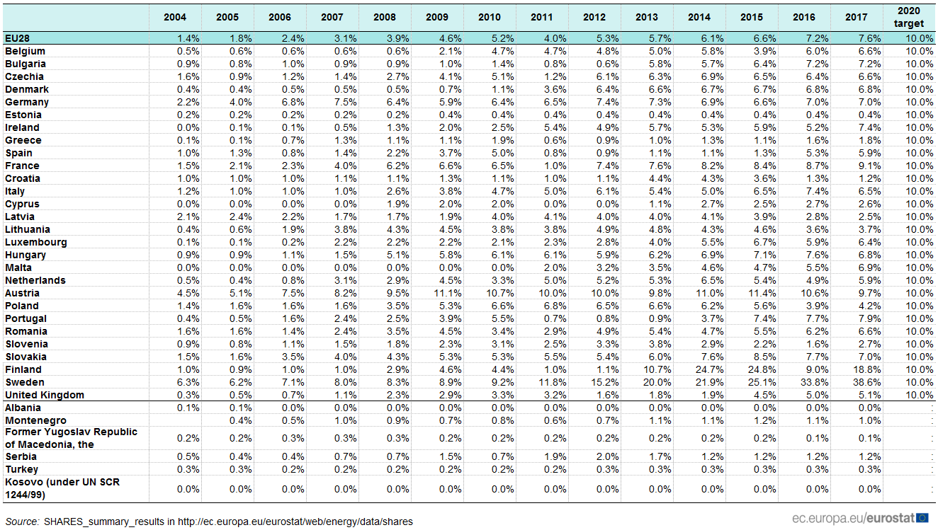
Cite this chapter
Evtimov, I., Ivanov, R., Stanchev, H., Kadikyanov, G., Staneva, G., Sapundzhiev, M. (2020). Energy Efficiency and Ecological Impact of the Vehicles. In: Sładkowski, A. (eds) Ecology in Transport: Problems and Solutions. Lecture Notes in Networks and Systems, vol 124. Springer, Cham. https://doi.org/10.1007/978-3-030-42323-0_4
Download citation
DOI: https://doi.org/10.1007/978-3-030-42323-0_4
Published:
Publisher Name: Springer, Cham
Print ISBN: 978-3-030-42322-3
Online ISBN: 978-3-030-42323-0
eBook Packages: EngineeringEngineering (R0)