
Abstract
Some key techniques should be constituted focusing on the difficult problems in the rolling stock developments and operations for light freight rails, by which the commercial velocity can be raised respectively to 160/250 km/h when running crossover the three main lines of present normal-speed rails or the permissible ballast tracks of newly-built high-speed rails with the cargo distribution capacity promotion and the considerable profit expectation from medium/long-distance transportations. By applying the traction-rod inner design with both bogie cradle and mono traction-rod device, the rapid freight bogies have been evolved to bolsterless ones from bolster ones. To take the secondary rubber stacks instead of the airspring suspensions, \( K_{2} \gg K_{1} \), the simulation analyses of rigid-flex coupling vibrations indicate that the current technical condition is not sufficient, in which the non-linearity influences of bogies to carbody interface can be caused therefore, and the non-linearity effects of mono traction-rods can also be introduced to the longitudinal and lateral stiffness of secondary suspensions. As a result the carbody shaking phenomenon will be produced with the dramatic impacts to wheel-rail contact wear and light-weight carbody elastic vibrations. If changing to the use of Japanese airsprings, the optimal configuration of bolsterless bogie was formulated with actively sharing the technical achievements from the economical operations of rapid passenger rails, by which the rolling stock for light freight rails can be running on the extended routing crossover different-graded lines, so as to increase the availability of mobile equipments and to decrease the depreciate rate.
Access provided by Autonomous University of Puebla. Download conference paper PDF
Keywords
1 Introduction
The speeding-up practices for light freight rails, i.e. the normal axle-load is ca. 18 t and the minimum one ≥(8.0–9.0) t in tare loopback, need the different kinds of rolling stock developments and operations, including the rapid freight covered car with fully-movable sidewalls, and the other special railway vehicles for the car-like valuable products to be rolling on/off or the fresh goods to be transporting in cold chain. So the developments of rapid freight bogies should explore the rational technical potentials for the light-weight carbody improvements. Otherwise, the serious non-linearity vibration influences will be occurring when the rapid freight bogies can not go in the opposite directions.
In the present developing situation, the rapid freight bogies are tending to the technical characteristics of passenger bogie like 25T [1, 2], e.g. frame bogie, axle-box suspension with arm positioning and mono traction-rod. So the innovative design of secondary suspension becomes one of outstanding disputed questions, including the adoption necessities of anti-yaw dampers and airspring suspensions, but the debate of which has to be taking account of the following two particularities:
-
(1)
three important technical requirements, which ought to be satisfied in the developments of rolling stock, i.e. (i) to increase the rated loading weight, (ii) to promote the cargo distribution capacity and (iii) to raise the profit expectation from medium/long-distance transportations. E.g. the light-weight design of covered car with fully-movable sidewalls, the trade-off has to be made rationally between the combination structure stiffness ununiformity of ca. 24 m long floor frame and the hyperstatic structure deformation coordination of slender roof supported with two end-walls and arch mid-frame [3].
-
(2)
low dynamical interaction in tare loopback, which is one of difficult challenges when running on the extended routing crossover the permissible ballast tracks of newly-built high-speed rails [4, 5]. E.g. flat car without containers, the hunting evolution of which will take place from carbody instability to bogie one due to the rolling moment of inertia decreased rapidly. Meanwhile the freight trainsets are impossible to meet the above three important technical requirements at all, e.g. Fuxing EMU with all seat removal can only have ca. 5 t loading weight.
The rigid-flex coupling simulations for large and complex systems are necessarily adopted so as to settle down the disputes in the innovative design of secondary suspensions. Considering some problems of typical mechanics [6], like hyperstatic structure or structural instability, the refined MBS models of railway vehicle will attach more importance to the system non-linearities generated by the complex interface of bogies to carbody, e.g. the functional differences of mono/dual traction-rod device, instead of simply extending the frequency range for the elastic vibration evaluation [7].
The dynamical design of rapid freight bogies is applying by the rigid-flex coupling simulations with the successful experiences being shared actively earned from the HSR economical operations. E.g. the economic design of Japanese Shinkansen bogie is accompanying with the 1st vertical bending modal vibrations of light weight carbody, if the full motor/trailer bogie is taken as a Dynamic Vibration Absorber (DVA) [8], the impacts of dynamical interactions will be neglected willfully come from the worn wheel-rail contact due to bogie instability problem and the thermodynamic non-linearity influences produced by Japanese airsprings thereby. But for the comprehensive performance design of ETR serial bogies, the novel anti-yaw dampers are adopted with dual-circulation working principle, λe = (0.06–0.35) [9], and the wheelset re-profiling period is extended reasonably to (250–300) thousand km. So the integrated innovative achievements can be constituted with combination of both technical features in order to meet the challenges of low dynamical interaction.
For the integrated system of full-vehicle service, the two main non-linearity influential factors should be taken separately as input/correlative excitations, which are generated from the worn wheel-rail contact and the bogie suspension. And the mutual transformation condition can be determined correctly between the regular/singular perturbations through the accurate analyses of inner forces for complex constraints. The disputes in the innovative design of secondary suspension can be therefore resolved satisfactorily by applying the dialectical methodology.
2 Regular/Singular Perturbations and Mutual Transformations
For the open cars, the locking iron is necessarily adopted to prevent the bulk cargo scattered from the door bottom. The separate model of locking iron is established with the complicated force system, as shown in Fig. 1. And the locking iron is then excited at C.M. point with the lateral and vertical accelerations of carbody. The equivalent friction angle contrast for the original/improved designs indicates that, as shown in Fig. 2, the contact angle θ between hinge pin and inclined chute is one of sensitive factors to the locking iron stability. I.e. when θ is decreased from 15° to 4°, the safety margin of locking iron can be gained sufficiently.

Complicated constraints of locking iron and topological relation diagram

Equivalent friction angle φ contrast for original/improved designs
In other words, only if the disturbance of vertical force component becomes smaller at the hinge pin, the separate model of locking iron can satisfy the condition of motion consistency or model validity. As a result, the singular perturbation under the limit cycle stability is returning to the regular perturbation under the asymptotic stability, so as to prevent the locking iron to be creeping towards or overturned.
3 Non-linearity Influences to Rigid-Flex Coupling Vibration
The rigid-flex coupling simulation models are shown in Fig. 3 for the rapid freight covered car in tare/laden, and the following three important techniques are considered sufficiently for light-weight carbody design, i.e. combined structure of ca. 24 m long floor frame, hyperstatic structure of slender roof and wide door with plugging locks

Rigid-flex coupling simulation models of rapid freight covered car
.
-
(1)
Bolster bogie improved design. The anti-yaw dampers are necessarily adopted to replace the central bowl and side-bearings because of the bolster instability created in the bolster bogies. If the centering condition is not satisfied under the track irregularity disturbance, as shown in Fig. 4, the bolster instability can be caused due to the mechanical properties of secondary suspensions of rubber stocks. Consequently, the very serious wear problems will be then produced with wheelset eccentric wear or rail running wider strip, which lead to the input excitations.
Fig. 4. 
Bolster instability created in bolster bogies with secondary rubber stocks
-
(2)
Bolsterless bogie improved design. The rapid freight bogies have been evolved to the bolsterless ones from the bolster ones with anti-yaw dampers. When considering the secondary rubber stacks instead of the airspring suspensions, \( K_{2} \gg K_{1} \), as shown in Fig. 5a, the simulation analyses of rigid-flex coupling vibrations indicate that the current technical condition is not sufficient, in which the non-linearity influences of bogies to carbody interface can be caused therefore, and the longitudinal and lateral stiffness variations of secondary suspensions can also be introduced due to the mono traction-rods. As a result the carbody shaking phenomenon will occur with the dramatic impacts to wheel-rail contact wear and light-weight carbody elastic vibrations, which are the similar occurrences of FastTech 360 test train due to the thermodynamic non-linearity influences of Japanese airspring suspensions [8]. Since the very space limitation for the fore/rear ends, as shown in Fig. 5b, the 1st vertical bending modal frequency of floor frame is decreased to ca. 7.20 Hz when considering the reinforcement design of slender roof, as shown Fig. 5c.
Fig. 5. 
Non-linearity influences of secondary rubber suspension and mono traction-rod in tare


And the end torsion modal frequency (opposite direction) is increased from the inherent one ca. 17 Hz to ca. 20 Hz with the fixed interface constraint adoption of coupler boxes, as shown in Fig. 5d. Consequently, the local high stresses occur at the corners of roller holder, as shown in Fig. 6a and b, the stress concentration effects of which can be eliminated by the detailed design improvement. But the lateral modal resonances are produced on the most vertical plane of side-doors, as shown in Fig. 6c, which have the lower correlation with the original/enhanced plugging locks.

Negative effects of non-linearity influences to safety of wide side-doors
For the laden case, the 1st vertical bending modal vibration of floor frame can not be excited because of the constraint effects of integrated boxes to the floor surface. But the lateral accelerations become extremely stronger at the top of end-walls, as shown in Fig. 7, since the lateral dynamical loads of mono traction-rods lead to the correlative excitations.

Non-linearity influences of secondary rubber suspension and mono traction-rod in laden
4 Optimal Configuration of Bolsterless Bogie
If changing to the use of Japanese airsprings, the optimal configuration of bolsterless bogie should overcome the technical defaults of Japanese Shinkansen bogie design prototype, i.e. the wheel-rail matching condition for the specific serving lines with the economic velocity (200–250) km/h, λe = (0.03–0.20), MAX. 0.25 recommended.
The practices of light freight rails should share actively the technical achievements from the economical practice of high-speeding passenger rails. The regression conclusion to Maxwell model can be drawn from the testrig investigations with anti-yaw dampers of ETR serial bogies [9]. Through the parameter optimal configuration of bolsterless bogies, as shown in Fig. 8, the solution can be formulated properly based on the anti-hunting absorbing band mechanism, so as to avoid as possible the dynamical interaction problems of worn wheel-rail contact.

Anti-hunting absorbing band mechanism through parameter optimal configuration
The bolsterless bogies with optimal configuration have the following three main technical advantages:
-
(i)
reasonable extending wheelset re-profiling period, i.e. for λe = (0.05–0.30), MAX. 0.35 recommended, the stability properties and evolution patterns in full-vehicle tare loopback service are shown in Fig. 9a and b.
Fig. 9. 
Stability properties and evolution patterns in full-vehicle tare loopback service
-
(ii)
no impacts when speeding up, i.e. there are hardly any influences to the wheel-rail contact wear when running on the extended routing crossover the permissible ballast tracks of newly-built high-speed rails. Under the five supposed conditions of wheel-rail profile matching, as shown in Fig. 10, the wear index evolutions are assessed for the wheelset re-profiling period, as shown in Fig. 11.
Fig. 10. 
Equivalent conicity curve contrast
Fig. 11. 
Wear index evolutions for wheelset re-profiling period
-
(iii)
returning to unified or normative wheel-rail profile matching, i.e. the nominal equivalent conicity λeN can be decreased to 0.05 due to Japanese airsprings adopted in secondary suspensions. The influences of λe decrease to carbody yaw modes are shown in Fig. 12. And when λe = 0.03, the minimum margin is greater than 5%. For the safety sake, λeN = 0.05 for the tare loopback in the full vehicle service.
Fig. 12. 
Influences of λe decrease to stability properties and evolution patterns


In summary, the optimal configuration of bolsterless bogies is formulated with the dual traction-rod devices instead of mono ones, which can go in the opposite directions with the light-weight carbody design of light freight wagons. And the adoption necessity of anti-yaw dampers and Japanese airsprings are proved so as to satisfy the minimum axle-load conditions in tare loopback.
5 Light Freight Rails and Three Particular Demands
Different from the passenger/freight mixed transportations for normal-speed rails, the practices of light freight rails tend to be participated in Chinese logistic network in order to decrease the proportion 16% of GDP (Gross Domestic Product), furthermore the intelligent wagon concepts can be constituted for the future developments. So the following three particular demands should be stressed in the development and operation of light freight wagons:
-
(1)
Low bulk density. To balance the axle-load and the load-bearing per meter, the distance has to be extended between fore and rear bogies, e.g. rapid covered car, the ca. 24 m long floor frame is the combination structural design with the stiffness ununiformity.
-
(2)
Fast cargo distribution. The requirements for mechanized handling or rolling on/off has to be considered in the light weight carbody designs, such difficulties as hyperstatic structure, structural instability or wide door with plugging locks need to be solved through the collaboration efforts between carbody and bogie experts.
-
(3)
Considerable profit expectation. Considering the ‘door to door’ service advantages of road transportations, the considerable profit expectation of light freight rails only come from the medium/long-distance transportations.
6 Rapid Freight Bogie and Light Weight Carbody Designs
For the rapid freight bogie developments in European rails, there are two outstanding designs of lateral swung bolsters and rubber cushions under central bowl, by which the two issues have to be considered carefully as follows:
-
(1)
Side-bearing friction instability. Similar to the Y37 frame freight bogie, the suspending rings with articulated joints, as shown in Fig. 13, can be used so as to avoid the abrasion impacts. But the dynamical simulation analyses indicate that the side-bearing friction instability problem will take place on the lateral swung bolsters when speeding up 160/250 km/h.
Fig. 13. 
Passenger frame bogie with lateral swung bolster in Sweden rails
-
(2)
Vibration fatigue safety. For Leila frame freight bogie, as shown in Fig. 14a, the rubber cushion design under central bowl doesn’t need the traction-rod devices but the technical difficulties will be solved costly thereby. So the evolution design of 4L bogie is trying to use the special pyramid frame instead of rubber cushion, as shown in Fig. 14b, which is impossible to guarantee the vibration fatigue safety in both tare and laden conditions.
Fig. 14. 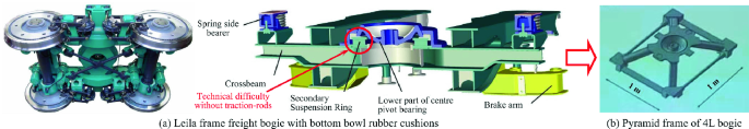
Leila freight frame bogie and 4L bogie evolution


As the three particular demands stated above, the light weight carbody designs for light freight wagons are more difficult than the ones for conventional freight wagons. If the lower dynamical interactions of wore wheel-rail contact can not be achieved in the tare loopback, the light weight carbody vibration will become stronger and stronger, by which the construction velocity (or design speed) will be decreased thereby. And the maintenance costs have to be paid highly under the unreasonable and unscientific maintenance system.
The availability and depreciation of mobile equipments are two important technical requirements for the light freight wagons. So the nominal equivalent conicity λeN is necessary to be decreased to (0.03–0.06), and the adaptability and friendliness can be improved therefore to different-graded railway lines. Esp. by applying the optimal configuration of bolsterless bogies with such technical features as dual traction-rod devices, anti-yaw dampers and Japanese airsprings, the minimum axle-load condition can be met satisfactorily in tare loopback.
7 Crossover Newly-Built Ballast Tracks
For the partial ballast tracks of Chinese newly-built HSR, the light freight wagons are permissible for the passenger/freight mixed transportations, but the running velocity (220–250) km/h must be guaranteed with no impacts to track lines. Furthermore, the inter-connectivity will be realized early between the present and newly-built railways, by which the constructions of economic corridors from western/middle areas to eastern coastal ones can be advanced rapidly.
Chinese HSR constructions are extended to the western/middle areas, in which (60–80)% capitals are the local investments from bank loans. Different from the European countries, the multi-level economic developments are still one of primary features in Chinese society. So the speeding up practices of light freight rails is one of important measures in promoting domestic demands. Otherwise, the serious cost increase of HSRS operations and maintenances will be transferred gradually into the heavy burden on the local economic developments along lines. Generally speaking, the above optimal configuration of bolsterless bogies is one of integrated innovative achievements in combination of Japanese Shinkansen and European rails [10].
8 Conclusion
The anti-yaw dampers and airsprings are necessarily adopted in the innovative design of secondary suspension for rapid freight bogies, so as to explore the technical potentials for the above technical requirements to be satisfied in the light-weight carbody design. And the integrated innovative achievements can be constituted by the combination of both technical characteristics come from the Japanese/European rails.
The regular/singular perturbations can be transformed conditionally, which is one of important dialectical methodologies in transacting the system non-linearities. Considering the quality and profit of light freight rails, the above three technical requirements will be therefore satisfied only by applying the dynamical design of light-weight carbody with the optimal configuration of bolsterless bogies.
References
Xu, S.F., Shao, W.D., Hu, H.B., et al.: The present conditions and development of technology in rapid freight car bogie in China and abroad. Roll. Stock 53(12), 4–9 (2015). (in Chinese)
Final Report Summary - SUSTRAIL (The sustainable freight railway: designing the freight vehicle – track system for higher delivered tonnage with improved availability at reduced cost). European Commission. http://cordis.europa.eu/result/rcn/175530_en.html
Yang, J., Piao, M.W., Fang, J., He, M.S., Li, H., Yu, Y.B.: Investigation of general mass and correlative excitation influences to rapid freight covered car rigid-flex coupling system. In: Proceedings on 25th International Symposium on Dynamics of Vehicles on Roads and Tracks (IAVSD 2017), pp. 785–790. CRC Press/Balkema - Taylor & Francis Group (2018)
Frőhling, R., Ekberg, A., Kabo, E.: The detrimental effects of hollow wear—field experiences and numerical simulations. Wear 265, 1283–1291 (2008)
Zhou, Q.Y., Liu, F.S., Zhang, Y.H., et al.: Solutions for problems at wheel-rail interaction in high speed railway. China Railw. Sci. 38(5), 78–84 (2006). (in Chinese)
Preumont, A.: Twelve lectures on structural dynamics. In: Solid Mechanics and Its Applications, vol. 198. Springer, Berlin (2013)
Koganei, R., Watanabe, N.: Expansion of frequency range for elastic vibration evaluation in hardware in the loop simulation systems for railway vehicles. Q. Rep. RTRI 56(2), 91–97 (2015)
Aida, K., Tomioka, T., et al.: Development of displacement-dependent rubber bush for yaw damper to prevent carbody vertical vibration. Q. Rep. RTRI 58(3), 182–188 (2017)
Bruni, S., Belforte, P., et al.: Experimental investigation of yaw damper performances: an improved and harmonised testing methodology developed within ModTrain EU project. In: Proceedings of WCRR 2008 International Conference, Seoul (KR) (2008)
Yang, J.: Studies and applications on dynamical design methodology of bogie and rigid-flex coupling simulation for full-assembled vehicle, pp. 52–54. Dalian Jiaotong University (2018). (in Chinese)
Funding
This work was supported by National Key R&D Program of China [number 2017YFB1201302-11].
Author information
Authors and Affiliations
Corresponding author
Editor information
Editors and Affiliations
Rights and permissions
Copyright information
© 2020 Springer Nature Switzerland AG
About this paper

Cite this paper
Li, Tt., Piao, Mw., Li, H., He, Ms., Xu, Sf. (2020). Contrastive Studies on Non-linearity Vibration Influences to Rigid-Flex Coupling System of Rolling Stock for Light Freight Rails. In: Klomp, M., Bruzelius, F., Nielsen, J., Hillemyr, A. (eds) Advances in Dynamics of Vehicles on Roads and Tracks. IAVSD 2019. Lecture Notes in Mechanical Engineering. Springer, Cham. https://doi.org/10.1007/978-3-030-38077-9_59
Download citation
DOI: https://doi.org/10.1007/978-3-030-38077-9_59
Published:
Publisher Name: Springer, Cham
Print ISBN: 978-3-030-38076-2
Online ISBN: 978-3-030-38077-9
eBook Packages: EngineeringEngineering (R0)