
Abstract
Coding techniques in Verilog HDL of finite state machines (FSMs) for synthesis in field programmable gate arrays (FPGAs) are researched, and the choice problem the best FSM coding styles in terms of an implementation cost (area) and a performance (speed) are considered. The problem is solved empirically by executing of experimental researches on the FSM benchmarks. Seven coding styles in Verilog are offered for coding of combinational circuits for FSMs from those two best styles are selected. On the basis of these two coding styles of combinational circuits six coding styles of FSMs are offered. The efficiency of the coding styles was researched for the synthesis of FSM benchmarks in two classes of programmable devices: CPLD (Complex Programmable Logic Device) and FPGA. The experimental results showed that the choice of coding styles allows to reduce the implementation cost of FSMs by a factor of 3.06 and to increase the speed of FSMs by a factor of 1.6. In conclusion, the prospective directions for coding styles of FSMs are specified.
Access provided by Autonomous University of Puebla. Download conference paper PDF
Keywords
- Finite state machine
- Field programmable gate array
- Coding styles
- Verilog
- CPLD
- FPGA
- Implementation cost
- Speed
- CAD
1 Introduction
Hardware Description Languages (HDLs) have a pivotal role in computer aided design (CAD). In CAD, today two HDLs are widely used: Verilog and VHDL. Verilog has been created by developers of CAD tools as an alternative of VHDL and it quickly became popular among digital logic engineers. As of now Verilog has several standards, which are supported by most vendors of CAD. Today, Verilog is supported by CAD tools of such firms as Intel, Xilinx, Synopsys, Cadence, Mentor Graphics, etc.
A finite state machine (FSM) is one of the most important components in the design of a sequential circuit. The efficient Verilog coding styles are necessary to infer synthesizable FSM from a project code. However, the Verilog standards do not give the answer to a question: how to code the FSM in Verilog.
To date, there are few studies that have investigated the coding styles of FSM in Verilog for synthesis in programmable devices. In [1], the encoding styles of the FSMs in Verilog and VHDL which are provided in design tools from Synopsys are considered. The general principles of representation of FSMs in the HDL languages are stated; two structural models are offered: with two and with one combinational circuit; different ways of state encoding are described: binary, one-hot, and almost one-hot. It also is considered using case and if statements for the description of the transition functions in different ways of state encoding, the error recovery and illegal states, asynchronous inputs, and unknown inputs.
In [2], the standardized FSM coding style in Verilog that is used in Cisco design tools is considered. In this style, the description of FSM transitions is carried out by case statement, the states are declared by local parameters, the FSM transitions are described by means of two variables: current and next. Using the compiler directives cisco_fsm is presented. The application of the offered standardized style of the FSM allows to analyze accessibility of each state, to find terminal states (from which there are no exits), to carry out a dynamic FSM verification, and to build a state diagram.
The FSM coding styles of [1] are detailed and extended in [3]. In [3], the two FSM coding styles are considered: with one and two processes; for each used style its advantages and shortcomings are noted; the possible ways of state encoding are described; the use of Synopsys FSM Tool for generation binary, Gray, and one-hot coding is discussed. The coding style for synthesis of register outputs of the Mealy FSM is offered.
The FSM coding styles of [3] have been developed in [4]. In [4], it is offered to use register outputs of FSM to eliminate glitch upon transitions between states. Two methods are for this purpose offered. The first method repeats the method [3] for the installation of registers on outputs of the Mealy FSM. In the second method, the output values of the Moore FSM are used for state encoding.
In [5], the five FSM coding styles are offered: style 1 with three processes for Mealy and Moore machines; style 2 and 3 with two processes for Mealy and Moore machines; style 4 with one process for Moore machines, and style 5 with two processes for Moore machines. The question what of FSM coding styles is better is set, but the answer to this question is not provided.
In [6], the FSM coding styles in Verilog and the different ways of state encoding that implemented in design tool ISE from Xilinx are investigated. Experimental researches were conducted for FPGA Spartan-6. Three FSM coding styles are considered: with one, two, and three processes; and also the next ways of state encoding are considered. The experimental researches have been conducted for one simple FSM example, which has one input, one exit, four states and five state transitions. Following parameters were analyzed: the number of used flip-flops, the number of used FPGA logic elements, and the maximum frequency of FSM. In [6], the following conclusions are drawn: for speed optimization prefer one-hot and speed1 option, and for area optimization chose gray or Johnson or sequential encoding scheme.
Overall, these studies indicate that most studies in the field of FSM coding have only focused on coding styles that have been implemented in CAD tools. Such approaches, however, have failed to address all coding styles which are possible in Verilog.
In this paper, we study the coding styles of FSMs in Verilog that can differ from the traditional coding styles. A problem is to choose a best coding style for an optimization of the area and the speed of FSMs. The problem is solved empirically by fulfilment of a great number of experimental researches. The received results give recommendations that allow to reduce considerably the FSM area and to increase the FSM speed without the application of any special synthesis methods.
2 FSMs with Three and Two Processes
Two types of FSMs are most known: Mealy machines and Moore machines. Previous studies showed that there are three main coding styles of FSMs in Verilog: with three processes, with two processes, and with one process, where the process is the always block in Verilog.
Coding of the FSM by one process is possible only for Moore machine, and as the Mealy machine is the most general model of the FSMs, in this paper we will study only two coding styles: with three processes and with two processes.
In the FSM coding style with three processes, the first process describes a combinational circuit \( {\text{CL}}_{{\varphi }} \) , which implements the state transitions, the second process describes a combinational circuit CLψ, which implements the FSM outputs, and the third process describes the FSM memory. In the coding style with two processes, the first and the second processes are combined in one process.
Before proceeding to examine coding styles of FSMs, we will study coding styles of combinational circuits for FSMs.
3 Coding Styles of Combinational Circuits for FSMs in Verilog
In general, Verilog does not superimpose any restrictions on the coding styles of FSMs, therefore we can use any Verilog statements and any constructions of these statements. Commonly, to check that the FSM is in a certain state the case statement is used, and to check transition conditions from some state both the if statement and the case statement can be used. We will consider various ways of usage of if and case statements for check of transition conditions and for forming FSM outputs.
Developers of the Verilog compilers recommend in the description of FSMs to use constructions else and default in if and case statements, and besides as the next state specify the present state in the constructions else and default. For completely specified FSMs [7], the usage of the additional else and default constructions does not influence in any way behavior of the FSM because this constructions will never be executed. For incompletely specified FSMs [8], the usage of the additional else and default constructions determines indefinite transitions from each state by the transition to the present state. Actually, the incompletely specified FSM is replaced by the completely specified FSM. Since for incompletely specified FSMs it is guaranteed that on the FSM inputs never there will be the vectors corresponding to the indefinite transition conditions, such additional definitions do not influence behavior of the FSM. Thus, the use of the else and default constructions do not influence on behavior of the FSM, however it allows to reduce sometimes the implement cost of the combinational circuits \( {\text{CL}}_{{\varphi }} \) and CLψ.
We will study the possible constructions of the if and case statements for assignment of the values to the output vector out depending on the values of the input vector in. In case of determination of the next state, the constructions of the if and case statements have similar forms.
The following variants of the usage of the if statement for coding the FSM combinatorial circuits are possible:
-
(1)
IF_1 – the check of each transition condition by means of the separate if statement (it is considered that the given approach leads to of the minimum implementation cost):

-
(2)
IF_2 – the check of the first transition condition from some state by means of the if statement, and the check of each following transition condition by means of the construction else if (the traditional approach for coding incompletely specified FSMs):

-
(3)
IF_3 – this variant repeats the previous case except that the last transition condition from some state is implemented by means of the construction else (the traditional approach for coding completely specified FSMs):
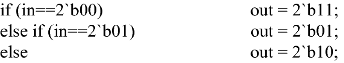
-
(4)
IF_4 – this variant repeats the construction IF_2 except that the construction else is added, which implements the transition to the present state (in coding transition functions), and the zero or unknown output (in coding outputs):


Similarly, following variants of the usage of the case statement for coding the FSM combinatorial circuits are possible:
-
(5)
CASE_1 – the check of each transition condition by means of the separate case item (the traditional approach for coding incompletely specified FSMs):

-
(6)
CASE_2 – this variant repeats the previous case except that the last transition condition from some state is implemented by means of the construction default (the traditional approach for coding completely specified FSMs):

-
(7)
CASE_3 – this variant repeats the CASE_2 construction except that the construction default is added, which implements the transition to the present state (in coding transition functions), and the zero or unknown output (in coding outputs):


Note that in coding the transitions in the construction IF_4 after last else and in the construction CASE_3 after default, it is described the transition to the present state, and also here can it is described the transition to the initial state or to the recovery state. Thus, we have 7 the coding variants in Verilog of the combinative circuits of FSMs.
In Listing 1, the variant IF_1 is used for check of three transitions conditions from some state. The clk and reset inputs are included in this code to simulate switching between states, and also the code contains a process for the generation of outputs. The examples of usage for other variants the if and case statements for a check of the transition conditions are built similarly.

To estimate the efficiency of the Verilog constructions that can be used for coding combinational circuits of FSMs we will consider 19 examples. Each example differed from another by the number of the checked conditions. The synthesis of combinational circuits was made for FPGA families Cyclone III by Quartus version 17.1, all options of synthesis were assigned by default.
The experimental research results for the implementation cost (the number of used logic elements of the FPGA) are presented in Table 1, where ex_n is the name of a example; n is the number of the checked conditions, n ∈ [3, 21]; IF_1, …, IF_4 are the coding variants with the if statement; CASE_1, …, CASE_3 are the coding variants with the case statement; Cmax and Cmin is the maximum and minimum implementation cost of the example for various coding variants; mid is the arithmetic mean value.
Table 1 shows that the coding variants IF_3 and IF_4 with the if statement, and also the coding variants CASE_2 and CASE_3 with the case statement produce the identical results. The coding variants IF_3 and IF_4 produce the best results at implementation cost, the variants CASE_2 and CASE_3 follow them. One interesting finding is that the worst results are received by means of the IF_1 variant, which was considered earlier as the best at implementation cost.
The results of this investigation show that the coding styles of combinational circuits of FSMs appreciably influence on the implementation cost. This fact is proved by relation Cmax/Cmin, which equal to 2.73 on average and 3.4 at maximum.
To create the FSM coding styles, we select the constructions IF_4 and CASE_3 because these constructions provide the low implementation cost and provide additional possibilities for FSM coding.
4 Coding Styles of FSMs
We consider two main coding styles of FSMs in Verilog: with three processes and with two processes. The description of FSMs with three processes contains first process for the description of the combinational circuit \( {\text{CL}}_{{\varphi }} \), which implements the transition functions, the second process for the description of the combinational circuit CLψ, which implements the output functions, and the third process, which implements the FSM memory. In the FSM description with two processes, the combinational circuits \( {\text{CL}}_{{\varphi }} \) and CLψ are represented by means of one process.
Each combinative circuit of the FSM is described or by means of the construction IF_4 with if statement, or by means of the construction CASE_3 with case statement. In this way, we can build six coding styles M_1, …, M_6 of FSMs, which are given in Table 2.
Note that the coding style M_1 corresponds to the traditional style of coding of FSMs with three processes, and the coding style M_5 corresponds to the traditional style of coding of FSMs with two processes.
The fragments of FSM coding for IF_4 and CASE_3 constructions are shown in listing 2 and 3 accordingly. Here in construction CASE_3, the casex statement is used instead the case statement because input vectors of FSMs can contain don’t care values.


5 Experimental Research Coding Styles of FSMs
To estimate the efficiency of the offered FSM coding styles in Verilog we used MCNC benchmarks of FSMs [9]. The synthesis of FSMs was fulfilled for three FPGA families which are related to three classes of programmable devices: MAX II family is Complex Programmable Logic Devices (CPLD), Cyclone III and Stratix III family is Field Programmable Gate Arrays (FPGA). The synthesis of the FSMs was made by Quartus tool with the parameters of logical synthesis that set by default.
Criteria for selecting the best coding styles were as follows: the FSM implementation cost (the number of used logical elements of the FPGA) and the FSM speed (the maximum frequency of the FPGA). Note that the coding style influences not all benchmarks of FSMs. The coding styles make noticeable impact on the implementation cost or the maximum frequency only in 23 FSM benchmarks from 44. Therefore such examples were researched, for which the implementation cost or the maximum frequency was changed.
The results of the experimental research for the FSM implementation cost and for the FSM speed of family MAX II are presented in Tables 3 and 4 respectively, where C_n is the implementation cost (the number of logic elements of FPGA) and F_n is the speed (in MHz) of the FSM that coded by style M_n, n ∈ [1, 6]; Cmin, Cmax, Fmin, and Fmax are the maximum cost, the minimum cost, the maximum speed, and the minimum speed of same benchmark for various coding styles; Cmax/Cmin, Fmax/Fmin are the relation of corresponding parameters.
The analysis of Table 3 shows that for FPGA family MAX II the relation between the maximum and minimum implementation cost of the FSMs is equal to 1.26 on average and to 3.06 at maximum (the example S208). Table 4 shows that for FPGA family MAX II the relation between the maximum and minimum speed of the FSMs is equal to 1.21 on average and to 1.60 at maximum (the example DK14). For family MAX II, the coding style M_6 is the best at implementation cost, and the coding style M_2 is the best at speed.
Similar experimental researches also were made for families Cyclone III and Stratix III. Table 5 provides the generalised results of the experimental researches of the FSM benchmarks, where Cmax/Cmin is the relation of the maximum and minimum implementation cost of the FSMs for various coding styles; Fmax/Fmin is the same, only for FSM speed.
Table 5 shows that by a choice of the FSM coding style, the implementation cost can be reduced by a factor of 3.06 for family MAX II, by a factor of 2.5 for family Cyclone III, and by a factor of 1.69 for family Stratix III. Similarly, the FSM speed can be increased by a factor of 1.6 for family MAX II, by a factor of 1.46 for family Cyclone III, and by a factor of 1.33 for family Stratix III.
The best coding styles at implementation cost and at speed for the FPGA families are presented in Table 6, where M_1 is the FSM coding with three processes when the next-state logic and the output logic is described by means of construction IF_4 (if … else if … else); M_2 is the FSM coding with three processes when the next-state logic is described by means of construction CASE_3 (case (…) … default: …), and the output logic is described by means of construction IF_4; M_4 is the FSM coding with three processes when the next-state logic and the output logic is described by means of construction CASE_3; M_6 is the FSM coding with two processes when the next-state logic and the output logic is described by means of single construction CASE_3.
Surprisingly, only one traditional FSM coding style M_1 (from six offered) is in Table 6, which provides the maximum speed for family Stratix III.
The fulfilled researches showed that coding style of FSMs in Verilog makes essential impact as on the FSM implementation cost (for separate examples by a factor of 3.06), and on the FSM speed (for separate examples by a factor of 1.6). Therefore in packet ZUBR [10] the program has been developed, which allows to form automatically the FSM code in Verilog from the FSM representation in language KISS2 [9]. The program allows to generate the FSM codes in Verilog according to offered coding styles M_1, …, M_6 and to select from them the most suitable description at the FSM cost and the FSM speed.
6 Conclusions
This study has shown that Verilog gives a great variety of the FSM coding styles, which are researched till now not completely. This project is the first comprehensive investigation of the FSM coding styles in Verilog. The traditional coding styles of FSMs not always are the best at the implementation cost and the speed. The results of this investigation show that the offered coding styles of FSMs in Verilog considerably influences on the FSM cost (for our examples by a factor of 2.71 on average) and on the FSM speed. The second major finding was that the FSM coding styles allow to reduce the FSM implementation cost and to increase the FSM speed without using any synthesis methods of FSMs. The findings of this study have a number of important implications for future practice. The present study lays the groundwork for future research into finding the coding styles of FSMs.
A limitation of this study is that all possible the coding styles of FSMs in Verilog are researched not. In particular, such coding styles were not considered as an implicit FSM coding, using assign statements, coding the FSM in the form of several separate modules (for example, the combinational circuit and the register), etc.
Traditionally, the check of the FSM present state is made by case statement (and also in the given paper), but with the same purpose it is possible to use various constructions of if statement. The important problem also is research of coding styles for Moore machines, as the model of the Moore machine of widely is used and it is very popular among developers. The offered technique of creation and choice of effective coding styles of FSMs in Verilog is applied for FPGA from Intel. Similar researches can be made for FPGA from the other vendors. The similar technique can be used also for research of coding styles of FSMs in VHDL. All these problems demand the further careful research.
References
Golson, S.: State machine design techniques for Verilog and VHDL. Synopsys J. High-Level Des. 9, 1–48 (1994)
Wang, T.H., Edsall, T.: Practical FSM analysis for Verilog. In: Verilog HDL Conference and VHDL International Users Forum (IVC/VIUF), Santa Clara, USA, pp. 52–58 (1998)
Cummings, C.E.: State machine coding styles for synthesis. In: Synopsys Users Group (SNUG 1998), San Jose, USA, pp. 1–20 (1998)
Cummings, C.E.: Coding and scripting techniques for FSM designs with synthesis-optimized, glitch-free outputs. In: Synopsys Users Group (SNUG 2000), Boston, USA, pp. 1–12 (2000)
Lee, J.M.: Verilog Quick Start. A Practical Guide to Simulation and Synthesis in Verilog, 3rd edn. Kluwer Academic Publishers, New York (2002)
Uma, R., Dhavachelvan, P.: Finite state machine optimization in FPGAs. In: Second International Conference on Computational Science, Engineering and Information Technology (CCSEIT-2012), Coimbatore, India, pp. 205–211 (2012)
Klimovich, A.S., Soloviev, V.V.: Minimization of mealy finite-state machines by internal states gluing. J. Comput. Syst. Sci. Int. 2, 244–255 (2012)
Klimovicz, A.S., Solov’ev, V.V.: Minimization of incompletely specified Mealy finite-state machines by merging two internal states. J. Comput. Syst. Sci. Int. 3, 400–409 (2013)
Yang, S.: Logic synthesis and optimization benchmarks user guide. Version 3.0. Technical report. North Carolina. Microelectronics Center of North Carolina (1991)
Salauyou, V., Klimowicz, A., Grzes, T., Bulatowa, I., Dimitrowa-Grekow, T.: Synthesis methods of finite state machines implemented in package ZUBR. In: Sixth International Conference Computer-Aided Design of Discrete Devices (CAD DD’7). Minsk, Republic of Belarus, pp. 53–56 (2007)
Acknowledgements
The present study was supported by a grant S/WI/3/2018 from Bialystok University of Technology and founded from the resources for research by Ministry of Science and Higher Education.
Author information
Authors and Affiliations
Corresponding authors
Editor information
Editors and Affiliations
Rights and permissions
Copyright information
© 2019 Springer Nature Switzerland AG
About this paper

Cite this paper
Salauyou, V., Zabrocki, Ł. (2019). Coding Techniques in Verilog for Finite State Machine Designs in FPGA. In: Saeed, K., Chaki, R., Janev, V. (eds) Computer Information Systems and Industrial Management. CISIM 2019. Lecture Notes in Computer Science(), vol 11703. Springer, Cham. https://doi.org/10.1007/978-3-030-28957-7_41
Download citation
DOI: https://doi.org/10.1007/978-3-030-28957-7_41
Published:
Publisher Name: Springer, Cham
Print ISBN: 978-3-030-28956-0
Online ISBN: 978-3-030-28957-7
eBook Packages: Computer ScienceComputer Science (R0)