
Abstract
Screening of peptides to find the ligands that bind to specific targets is an important step in drug discovery. These high-throughput screens require large number of structural variants of peptides to be synthesized and tested. This chapter describes the generation of arrays of peptides on Teflon-patterned sheets of paper. First, the protocol describes the patterning of paper with a Teflon solution to produce arrays with solvophobic barriers that are able to confine organic solvents. Next, we describe the parallel syntheses of 96 peptides on Teflon-patterned arrays using the SPOT synthesis method.
Access provided by CONRICYT – Journals CONACYT. Download protocol PDF
Key words
1 Introduction
Peptide-based therapeutics constitutes a significant fraction of new chemical entities and FDA-approved drugs. Discovery and optimization of peptide ligands that bind to specific targets require testing of a large number of structural variants of the peptides. Library-based methods, such as one-bead-one-compound combinatorial libraries (OBOC) [1] and genetically encoded libraries of peptides and peptides derivatives that are displayed on phage [2, 3], cells [4], or RNA [5], are useful for identification of “hit” peptide sequences from million to billion variants of peptide sequences. On the other hand, the process of hit-to-lead validation requires individual testing of the hit sequences. In this process, the array of peptide-derived ligands is a uniquely convenient tool because it allows parallel synthesis, characterization and testing of relatively large number of hits in uniform conditions. The array can be created by grafting pre-synthesized peptides onto a support at controlled locations [6, 7], or by stepwise assembling the peptides from amino acids directly an a planar support. To accelerate the latter method, Frank and coworkers [8] pioneered the synthesis of peptides as spots on cellulosic membranes (or paper). This solid-phase peptide synthesis method, dubbed as “SPOT synthesis,” was widely adopted in academic and industrial laboratories. It led to the development of commercially available technologies for synthesis of these arrays and to the establishment of service companies providing SPOT arrays on demand. The paper support was shown to be compatible with other classes of combinatorial synthesis to generate small-molecule arrays [9].
Unlike most syntheses on solid supports, which are conducted in stirred or flow-through reactors, in SPOT synthesis, the reagents are deposited onto the porous support to form “spots” of desired sizes. In these conditions, the reactions occur in a static, non-stirred volume of solvent in which the mixing of reagents is slow because it is limited to diffusion only. Moreover, it is problematic to deposit an excess of reagents to drive the reaction to completion, and evaporation of the limited amount of solvent during synthesis can pose a significant problem. To overcome these problems, we developed a method [10] to pattern paper with a solution that consists of a resin of amorphous fluoropolymer (e.g., Teflon solution from DuPont). Patterned Teflon-barriers resist solvent penetration and confine a broad range of organic solvents used in organic syntheses within the barriers. An excess of solvents, when deposited on the solvophilic zones of this Teflon-bound porous support, flows through the support and allows for performing synthesis in a flow-through fashion. The pattern of the porous support that consists of 96 squares (Fig. 1a) follows the exact foot print of a commercial 96-well plate, and this makes the Teflon-patterned array compatible with the use of standard plate-to-plate transfer robotics and plate readers for liquid handling and analysis.

(a) 96-square template for Teflon-patterned array. (b) Holder to clamp the paper for convenient handling. (c) Alternative holder for the paper made from bulldog clips
In this chapter, we first describe the steps for patterning the paper support with solvophobic barriers to generate Teflon-patterned arrays with 96 solvophilic zones for the peptide synthesis (Fig. 2). We then provide the details of the method for synthesizing the peptides on paper, which is an adaptation of the protocol published by Hilpert et al. [11]. We describe both the “manual” way, accessible with common equipment found in a chemical/biology laboratory, as well as a “semi-automated” method using a commercially available liquid handling workstation.

Step-by-step description of the Teflon-patterning process. (a) Wax-patterning of the paper, (b) spotting of the sucrose protective solution, (c) distribution of the Teflon solution made in HFE and (d) rinsing of the array after evaporation of the solvent (Reproduced from ref. [10] with permission from Wiley)
2 Materials
2.1 Reagents
-
1.
Teflon solution: 20 % Teflon® AF amorphous fluoropolymer resin (DuPont 400S2-100-1) in solution in methoxyperfluorobutane (Novec HFE-7100 Engineered fluid) (see Note 1 ).
-
2.
Sucrose solution (~2.5 mL per array): 1 g/mL of sucrose (or table sugar) in Milli-Q water.
-
3.
Amino acid stock solutions: Determine the need for each 9-fluorenylmethyloxycarbonyl-conjugated amino acid (or Fmoc(amino acid)-OH) for the peptide synthesis using Tables 1, 2, 3 and 4 described in the Subheading 3.3. Prepare a stock solution of each in 0.75 M in N-methyl-2-pyrrolidone (NMP). Store the stock solutions in amber glass vials at −20 °C for up to a week (see Note 2 ).
Table 1 Identification of the amino acids to be added at each cycle Table 2 Maps of the 96-zone array at each coupling cycle (left) Table 3 Calculation of the quantities of reagents for the coupling of the amino acids Table 4 Maps of the master plates prepared for the coupling of the amino acids for each cycle -
4.
HOAt stock solution: 1-hydroxy-7-azabenzotriazole (HOAt) at 2.25 M in NMP as indicated in Table 3.
-
5.
DIC stock solution: N,N′-diisopropylcarbodiimide (DIC) at 1.68 M in NMP as indicated in Table 3. The coupling reagent DIC may be substituted by another one, such as dicyclohexylcarbodiimide (DCC).
-
6.
First β-Ala functionalization solution (used for four arrays, see Note 3 ): dissolve 576 mg Fmoc-β-Ala-OH in 9 mL of dimethylformamide (DMF), add 270 μL of 1-methylimidazole and 337.5 μL DIC.
-
7.
Second β-Ala activated solution (used for four arrays, see Note 3 ): Dissolve 1261 mg of Fmoc-β-Ala-OH in 5.4 mL of NMP (or use the 0.75 M stock solution). Fifteen minutes before spotting, add 1.8 mL of HOAt solution (551 mg in 1.8 mL NMP or the 2.25 M stock solution) and 1.8 mL of DIC solution (475 μL of DIC plus 1325 μL NMP or the 1.68 M stock solution). Mix and let react for ~10 min.
-
8.
Capping A solution: 2 % (v/v) of acetic anhydride in DMF (typical volume prepared: 100 mL).
-
9.
Capping B solution (protect from light): 2 % (v/v) of acetic anhydride + 2 % (v/v) of N,N-diisopropylethylamine (DIPEA) in DMF (typical volume prepared: 50 mL).
-
10.
20 % Piperidine solution: 20 % piperidine in DMF (typical volume prepared: 200 mL).
-
11.
Cleavage A solution: Mix 90 % (v/v) trifluoroacetic acid (TFA), 3 % (v/v) triisopropylsilane (TIPS), 2 % (v/v) Milli-Q water, 1 % (w/v) of phenol, and 4 % (v/v) dichloromethane (DCM) (see Note 4 ). The typical volume is 60 mL for four arrays. WARNING: TFA and phenol are corrosive and toxic, so they should be handled with care.
-
12.
Cleavage B solution: Mix 50 % (v/v) TFA, 3 % (v/v) TIPS, 2 % (v/v) Milli-Q water, 1 % (w/v) of phenol, 44 % (v/v) DCM (see Note 4 ). The typical volume is 60 mL for four arrays. WARNING: TFA and phenol are corrosive and toxic, so they should be handled with care.
-
13.
Bromophenol blue staining solution (optional): 0.003 % (w/v) of bromophenol blue in methanol. Protect the solution from light.
2.2 Apparatus/Instruments
-
1.
Paper: the protocol and quantities are described for Whatman filter paper grade 50, but other cellulosic substrate can be used, although the spotting volume might need some adjustments.
-
2.
Solid ink printer (e.g., Xerox ColorQube 8570 series).
-
3.
Multichannel pipettors or fluid handling workstation (e.g., BioTek Precision XS).
-
4.
Frame holder to clamp the paper (Fig. 1b) or any reliable in-house made system to maintain the paper above the surface during deposition (e.g., clamps; Fig. 1c). Special holders are also available from SyntArray at www.syntarray.com.
-
5.
Common vials, glass bottles, reagent vessels, pipette tips, pipettors used for preparation of the solutions and distribution of reagents and solvents.
-
6.
A vacuum pump or aspirator to aspirate excess reagents from the paper after reaction (Fig. 3).
Fig. 3 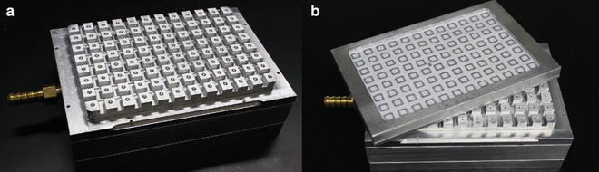
96-nozzle vacuum apparatus that allows simultaneous aspiration of reagents through the paper array from the 96 zones. It was custom-made to fit the dimensions of the SyntArray paper holder (Reproduced from ref. [10] with permission from Wiley)
-
7.
Small plastic bags to store the arrays (e.g., freezer bags, plastic bags).

3 Method
3.1 Patterning of Paper to Generate Solvent-Resistant Arrays
-
1.
Cut the paper into several 6″ × 11″ bands.
-
2.
Open a drawing file (see Note 5 ) with the desired pattern (e.g., 96-square, Fig. 1a; three arrays can fit on one band of paper). Print the pattern (without any scaling) on the paper using a solid ink printer.
-
3.
After printing the solid-ink pattern on the paper, place it in the oven at 120 °C for 5 min. This step yields a wax-patterned paper array [12] that has areas resistant to aqueous solutions (Fig. 2a) (see Note 6 ).
-
4.
Cut the paper along the red-colored frame (Fig. 1a). If you have a frame holder (Fig. 1b), place the paper in it. Alternatively, cut the printed paper array to the required dimensions and clamp it between two magnetic bulldog clips (Fig. 1c).
-
5.
Distribute 25 μL of the sucrose solution per zone using a multichannel pipette (the sucrose solution protects the non-waxed zones from impregnation with Teflon during the next step). Control the success of the deposition by ensuring the presence of the hemispherical drop on each zone (Fig. 2b).
-
6.
Distribute 3 × 800 μL of the diluted Teflon solution with a P1000 pipettor over the array (Fig. 2c). Ensure that the Teflon solution covers the entire array; all the areas around the zones with the drop of sugar on the paper should appear uniformly translucent. Pay special attention to the area of the paper along the holder because this is where the deposition of Teflon commonly fails (see Note 7 ).
-
7.
Evaporate the solvent to allow for the formation of a Teflon film on the paper. The best method is air-drying the paper at room temperature for ~1 h. When working with more than one array, each one should have 2 in. of space above and below it for proper air circulation (see Note 8 ).
-
8.
Once the solvent evaporated, the areas of paper patterned with Teflon have a bright white reflective appearance. At this point, remove the top part of the frame holder to dry the borders of paper that were blocked by the holder. Drying is complete when the marks of the borders are invisible. If necessary, the arrays can be left to dry overnight.
-
9.
Immerse the arrays in cold water for 15–20 min. Change the water twice to completely remove the protective sucrose solution (Fig. 2d) (see Note 9 ).
-
10.
Check the Teflon patterning for any defects: when the paper is wet, any defect should have a translucent appearance, instead of the bright white reflective appearance indicative of the Teflon-impregnated areas (see Note 10 ).
-
11.
Air-dry the arrays or use a heat gun to accelerate the drying.
-
12.
The arrays can be stored in sealed bags at room temperature for several months before use.
3.2 Functionalization of the Paper Array with a βAla-βAla Linker
The procedure is described for working with four arrays, since we recommend functionalizing by batches of at least four arrays. If more arrays (or less) are required, scale the reagents accordingly.
-
1.
Mark the top right corners of the Teflon-patterned arrays using a pencil to assist in remembering the orientation of the arrays throughout the synthesis.
-
2.
Place the arrays in a holder using a forceps handling only the edge of the array. Make sure that the array is centered properly in the holder and that there is equal empty space on all four sides of the array.
-
3.
Prepare the first β-Ala functionalization solution by dissolving the pre-weighed Fmoc-β-Ala-OH in DMF. Immediately before spotting, add 1-methylimidazole to the mixture, and mix by vortexing. Add N,N′-diisopropylcarbodiimide (DIC) and mix by vortexing again.
-
4.
Spot 15 μL of this functionalization solution on each zone on the paper array. Reaction will occur between Fmoc-β-Ala-OH and the cellulose structure of the paper (Fig. 4, reaction a).
Fig. 4 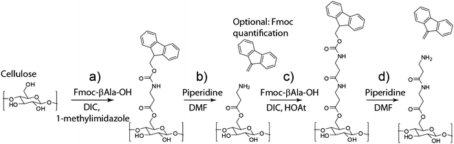
Functionalization of the paper with a βAla-βAla linker. (a) First β-Ala functionalization, (b) deprotection of the N-terminus of β-Ala, (c) second β-Ala activation, (d) deprotection of the N-terminus of βAla-βAla
-
5.
Stack up to 4 arrays on top of one another in the fume hood. Cover the arrays to prevent evaporation and allow the reaction to proceed in the dark for 3 h.
-
6.
Once the reaction is completed, place each array on top of a 96-nozzle vacuum apparatus (Fig. 3) and aspirate the reaction solution through each of the 96 zones on the paper using vacuum suction.
-
7.
To wash the zones, use a multichannel pipette to spot on each zone 15 μL of DMF from a vessel reagent or “boat” previously filled with 50 mL of DMF.
-
8.
Aspirate the wash solution through the paper, as previously described in step 6.
-
9.
Repeat steps 7–8 for a total of four washes.

PP (possible Pause Point): The synthesis can be interrupted between some steps of synthesis. When this happens, we denote it by PP (see Note 11 ).
-
10.
To deprotect the N-terminus of the β-alanine bound to the paper, spot 15 μL of solution of piperidine (a mild base) on each zone. For convenience, the piperidine solution as first put in a boat (1.5 mL per array, plus the adequate excess for the dead volume of the boat, for example 3 mL).
-
11.
Let the deprotection reaction (Fig. 4, reaction b) proceed for 5 min.
-
12.
Aspirate the solution, as previously described in step 6.
-
13.
Repeat steps 10–12 once to complete the deprotection reaction.
-
14.
Repeat steps 6–9 to wash the arrays.
-
15.
OPTIONAL: To verify the successful β-Ala functionalization of the paper, immerse the array in a container with the bromophenol blue solution (15 mL, poured in the container before to add the paper), and shake the container gently for 1–2 min until a blue color is visible. At this stage, the blue color, indicative of the presence of the amino group from β-Ala, should be uniform in every zone, confirming the successful functionalization of the array. Wash the paper array with 30 mL of methanol for 30 s to remove the blue dye and repeat this washing step four times, until no blue color is released from the paper (see Note 12 ).
-
16.
Allow the arrays to air-dry. If the wash solution is aspirated thoroughly, the arrays will dry within 5 min (see Note 13 ).
PP = Possible Pause Point (see Note 11 )
-
17.
Prepare the second β-Ala activated solution by dissolving the pre-weighed Fmoc-β-Ala-OH in NMP. Add the HOaT solution, mix by vortexing. Add the DIC solution and mix again by vortexing. Allow the activation of the amino acid by HOAt and DIC to proceed for 10 min before spotting.
-
18.
Spot 15 μL of solution on each zone.
-
19.
Allow the peptide coupling reaction (Fig. 4, reaction c) to proceed for 20–30 min, preferably in the dark, and then aspirate the excess solution through each zone.
-
20.
Prepare Capping solutions A and B or use the premade stock solutions.
-
21.
Spot 15 μL of Capping A solution on each zone.
-
22.
Allow the reaction to proceed for 5 min, and then aspirate the excess of reagent.
-
23.
Spot 15 μL of Capping B solution on each zone.
-
24.
Allow the reaction to proceed for 10 min, and then aspirate the excess of reagent.
-
25.
Wash the zones on the paper arrays by following steps 6–9.
PP = Possible Pause Point (see Note 11 )
-
26.
Deprotect the N-terminus of the second β-alanine by following the steps 10–16 (Fig. 4, reaction d).
-
27.
The arrays modified with the β-Ala-β-Ala linkers can be stored until use.
PP = Possible Pause Point (see Note 11 )
3.3 Construction of Tables for the Amino Acid Mapping and Automatic Calculations of the Required Reagents for Peptide Synthesis
To facilitate the calculation of the required volumes of amino acids solution, we describe the construction of a set of four tables using EXCEL. These tables yield the maps of the master plates with the required amount of reagents. This section describes in detail how to prepare these tables. Once the tables are constructed, they can be used with very minimal input from the user.
-
1.
Prepare a table to identify the amino acids required at each synthesis cycle. In Table 1, the user add in column C the sequence of the peptide (using the convention: Nterminus-XYZ-Cterminus) for each position indicated in columns A and B. The amino acid required for each cycle to synthesize the peptide (from the C-terminus to the N-terminus) is generated in columns D to R. The letter for each amino acid is extracted from the sequence, i.e., by using formula (1) for cell D3:
-
2.
Table 2 generates a map for each amino acid to be added at each position of the 8 × 12 array and a total counts for each amino acid per cycle. This second table is generated automatically from the sequences input in column C in Table 1 during step 1. A formula generates the map by copying the amino acid of each position from columns D to R of Tables 1 and 2, e.g., formula (2) for cell B2 in Table 2,
where $A$1 represents the cycle number, 3 + $A$1 the column number and (1 + $A2 + (B$1 − 1)*8) the row number in Table 1 from which the amino acid is imported. The term ($B1 − 1)*8 is required for arrays where different peptides are synthesized in one row as in the examples presented in Figure 5a and b.

The location of the replicates used on the array can easily be changed by modifying the numbers in row 1, columns B–M in Table 2: e.g., the 3 replicates are grouped in Figure 5c whereas the 2 replicates in Figure 5d are separatead to form two blocks displaying the 48 peptides.
For the next synthesis cycles, the only cell that requires modifications in the formula is the cycle number. For example, the formula (3) for cycle 2 (cell $A$11) for cell M19 is given by,
This table is particularly useful if the spotting of each activated amino acid solutions is performed manually because Table 2 can be used as a print-out map during the experiment.
A formula is required to calculate the number of occurrences of each amino acid in each cycle, e.g., to calculate for the 12 glycines needed in cycle 1, formula (4) for cell P4 of Table 2 is given by
where $B$2:$M$9 represents the range of the full map for cycle 1, and P3 is the cell containing the targeted letter for the amino acid counting (i.e., G).
-
3.
Table 3 calculates the amounts of each amino acid needed for a chosen set of synthesis cycles. Table 2 is based on the example presented in Figure 5a and c. The input of the user is limited to the following six cells: value of the first cycle number (B2) and last cycle number (C2), number of arrays synthesized (G2), volume of solution to be added on each zone (G1, this value can vary depending on the type of paper used), number of repetition of the coupling (J1, only change this value for special cases when the coupling reaction—see Subheading 3.4, step 6—is performed more than once at each cycle), and the dead volume of the used vessel (J2, typically for deep well plate, this value is 50 μL).
The “cycle” table on the right-hand side of Table 3 is constructed by repeating formula (4) indicating the letter of the amino acid from column M and adding two conditions (the IF functions) to ensure counting only the considered cycle if it is part of the range of cycles (e.g., 7 as defined in the range of cycles described by cells B2 and C2). For example, for cell AA6, there were 12 A (or alanine), see formula (5) as follows,
where AA$5 is the considered cycle (i.e., 2), $B$12:$M$19 the map of cycle 2 in the second table (values from the table in Figure 5c; cells not visible in the presented excerpt).
-
4.
Column A of Table 3 corresponds to the sum of all the amino acids counted in the “cycle” table described in step 3. For example, for cell A6, a value of 48 was obtained from formula (6) as follows
-
5.
The total volume of activated amino acid solutions required (see Subheading 3.4 steps 4–6) are calculated in column D, by combining the user inputs and the total amino acid occurrences from column A. For example, for cell D6, the value of 4800 μL was obtained from formula (7) as follows
where the factor 250/180 accounts for the excess volume, and the IF function is used to determine the number of wells of the master plate by dividing the total number of occurrences for each amino acid (A6) by the number of replicates of each peptide per array (here, three replicates are used for the 32 peptides, and so A6/3 is used), and to count the dead volume ($J$2) for each well.
-
6.
The amount of amino acids required to achieve a final concentration of 0.45 M in the activated amino acid solutions (amino acid solution mixed with HOAt and DIC) is calculated as follows: total volume (columnD) × molecular weight (columnC) × concentration with corrective factor for the units. The formula (8) for E6 is:
The amounts of the activator HOAt and coupling reagent DIC are calculated similarly with an additional reagent-specific factor (0.5 for HOAt and 0.25 for DIC [11]). The formulae (8′) and (8″) for F6 and H6 are given, respectively, by:
where $F$27 and $H$27 corresponds respectively to the molecular weight of HOAt (i.e., 135.1 g/mol) and the molecular weight of DIC divided by its density (i.e., 156.6 mL/mol).
-
7.
The volumes for individual reagents are calculated as fractions from the total volume: 3/5 for the amino acid solution (column K), 1/5 for HOAt solution (column G), and 1/5 for DIC solution (column J). Since DIC is a liquid, it is the sum of DIC volume (column H) and NMP volume (column I) which makes 1/5 of the total volume.
-
8.
The exact volumes of stock solutions of HOAt and DIC are then calculated in row 26; the row 28 contains the working volumes (i.e., the value in row is 26 × 1.2, where 1.2 is the excess factor).
-
9.
Table 4 calculates the amount of all the amino acids and reagents required for any particular synthesis cycle(s). A more compact table (Figure 6) can be created by hiding the cells of all the intermediates and focusing on the volumes of the reagents needed for the preparation of the solutions of activated amino acid.
Fig. 6 
Example of a compact version of Table 3. Cells needed for calculations were hidden. Only the required volumes of the amino acids stock solutions, HOAt stock solution, and DIC stock solution are displayed
-
10.
Table 4 generates the maps of master plates for each coupling cycle. Typically, multiple deep well plates contain the stock solutions of amino acid at 0.75 M, and the required amount of activator (HOAt) and coupling reagent (DIC) for each cycle, which will allow for the preparation of the activated amino acid solutions.

No input is required from the user in this table. The range of cycles is imported from Table 3 (cells B2 and C2), and the amino acid map for each cycle from the first table (in this example, we used values of the Figure 5a. For example, the formula (9) for cell C6 is as follows:
where the location of the amino acid for each well is defined from its row number ($O6) and the considered cycle (E$4). In this example, (2 + $O6),3 + E$4 corresponds to cell D3 of the table in Figure 5a, and reports a proline (or P).
The cycle numbers, as in cell E4 or I4 of Table 4, are displayed in correlation with the range of cycles selected using formula (10), which for cell I4 is as follows:
where the term $C$2 +1 is the cycle number (i.e., 2), and the term +1 needs to be incremented for each additional cycle. For example, for cell E37, the formula (10′) is given as follows:
-
11.
Finally, the volumes for the stock solutions of amino acid (G1) and the two other reagents (same volume for DIC and HOAt, so the same formula is used to display it in the last two columns of each deep well plate, e.g., cells M10 and N10 for the first cycle) are calculated from data of Table 3 with the following formulae respectively:
In formula (11), all the references to ‘Table 3’ were previously described in step 3. The ratio 250/180 accounts for an excess of liquid and the multiplier 3 represents the number of replicates to be spotted per array. The IF function in formula (12) counts the number of cycles in this particular deep well plate. In the example of Table 4, plate # 1 contains solutions for two cycles; whereas plate # 4 contains solutions for one cycle. The ratio 1/3 corresponds to the volume of reagent relative to the calculated volume of amino acid solution in cell G1 and the multiplier 4 represents the number of amino acid solutions to which the reagents need to be added.
3.4 Syntheses of the Peptides Through Successive Addition of the Amino Acids
-
1.
Calculate the amounts of amino acids and coupling reagents needed. Generate the maps of the master plates using Tables 1, 2, 3, and 4, as described in Subheading 3.3.
-
2.
Prepare the master plates (deep well plate) by filling each well with the required amounts of the stock solutions of amino acids, HOAt and DIC following the map of Table 4 (see Note 14 ).
-
3.
Dry the paper arrays completely prior to the coupling of the amino acids.
-
4.
Using an 8-channel pipettor, transfer the pre-calculated volumes of stock solutions (HOAt and DIC) to the wells of the master plate for the required cycle. In the specific example of Table 4: 60 μL of 2.25 M HOAt and 60 μL of 1.68 M DIC are added to the well containing 180 μL of amino acid solutions. Mix the solutions well by pipetting up and down multiple times.
-
5.
Allow the activation of the amino acid to proceed in the master plate for 10 min.
-
6.
Spot 15 μL of the activated amino acid solutions from the master plate onto the paper array(s) following the map of Table 2 using an 8-channel pipettor and allow the reaction to proceed for 30 min, preferably in the dark (see Note 15 ).
-
7.
Aspirate the excess solution, as described in step 6 of Subheading 3.2 (see Note 16 ).
-
8.
Cap the unreacted sites, as described in steps 20–25 of Subheading 3.2.
PP = Possible Pause Point (see Note 11 )
-
9.
Deprotect the N-terminus of the newly coupled amino acid, as indicated in steps 10–16 of Subheading 3.2 (see Note 17 ).
During the last washing step, the master plate that contains the solutions of amino acids for the next cycle can be warmed up to room temperature.
-
10.
Ensure that the arrays are completely dry, and then proceed to the next synthesis cycle by repeating the steps 4–9 until all amino acids are coupled.
3.5 Cleavage of the Side-Chain Protecting Group
-
1.
Thaw phenol at room temperature for 15 min before weighing it.
-
2.
Prepare the Cleavage A and Cleavage B solutions; the reagents must be added following the order given in Subheading 2.1. Slowly swirl the solution after each addition of reagents during the preparation.
-
3.
Place each array in an individual container (e.g., small polypropylene box or glass dish). Make sure the array face upwards using the pencil mark on the top right corner of the array. Add ~15 mL of Cleavage A solution to the container and submerge the array in it. If air bubbles are trapped under the array, lift the corner of the array with a forceps and submerge the array again until all bubbles disappear.
-
4.
Close each container and allow the cleavage reaction to proceed for 30 min in the dark.
-
5.
Open the container(s) and pour the excess Cleavage A solution into a designated waste disposal container (e.g., “corrosive”). Then, wash the arrays with 4 × 15 mL of DCM. (see Note 18 ).
-
6.
Repeat steps 3 and 4 with 15 mL of Cleavage B solution, but allow the reaction to proceed for 3 h instead of 30 min.
-
7.
Wash the arrays with 4 × 15 mL of DCM and 2 × 15 mL of ethanol. Air-dry the arrays in a fume hood.
-
8.
The arrays can be used for biological assays immediately or they can be stored at −80 °C until use.
3.6 Semi-automated Synthesis on Patterned-Paper Microarray
In this section, we described the adaptation of protocols detailed in Subheadings 3.1 and 3.2 to achieve an automated generation of paper arrays of peptides with a liquid-handling workstation (BioTek Precision XS). Examples of the programs for the workstation can be found in the supporting information of Deiss et al. [10]. We anticipate the user to be familiar with the general operation of the Biotek instrument as well as basic programming of the instrument and the associated terminology.
3.6.1 Automated Deposition of Teflon
-
1.
In the program, define the paper as a new receiving vessel, based on a 96-well plate format: add a vertical offset along the z-axis to define as the bottom of the vessel the height of the paper in the holder on the platform of the liquid-handling workstation.
-
2.
Adjust the specification files of the dispensing system to allow spotting of the solutions from a 5-mm height above the paper.
-
3.
Adjust the dispensing rate to 1 (the slowest) for the distribution of the viscous sucrose solution.
-
4.
Prepare a patterning program [10]. Aspirate with the 8-channel dispenser 8 × 100 μL of sucrose solution from a boat and dispense four times 8 × 25 μL in the first four columns. Loop three times to ensure deposition of sucrose solution on the 96 zones of the arrays. Dispense 20 μL of Teflon solution using the single-channel bulk dispenser between each zone using a horizontal offset; loop the dispensing 88 times. Dispense 25 μL of Teflon solution on the left and right side of the arrays using the same dispenser 8 times for each side. Repeat the program four times for the four positions of the paper arrays on the workstation.
-
5.
Follow steps 1–4 of Subheading 3.1 to prepare the paper array. Place four holders with wax-patterned paper arrays on the workstation matching the position of the receiving vessels. A stacker loaded with multiple holders can also be used for the automated deposition of Teflon on a larger number of paper arrays.
-
6.
Fill a boat on the workstation with 50 mL of the sucrose solution.
-
7.
For the distribution of the Teflon solution, a bulk dispenser is recommended as it allows the solution to be dispensed from a closed bottle, which prevents evaporation of the solvent.
Initialize the single-channel dispenser, use the “prime” function to rinse the tubing with 2000 μL of HFE-7100 (i.e., methoxyperfluorobutane). Then, prime the tubing with 1500 μL of Teflon solution.
-
8.
Load the Teflon patterning program prepared at step 4 and start the run.
-
9.
When the program has proceeded for the four arrays, the arrays can be put aside and a new batch of four arrays can be prepared by simply refilling the boat with the sucrose solution and starting the run again without unloading/reloading the program.
-
10.
Process the Teflon-patterned paper arrays, as described in steps 7–11 of Subheading 3.1.
-
11.
When finished with the full batch of arrays, clean the single-channel dispenser. This is achieved by purging 2000 μL back from the Teflon solution bottle, and priming it with 4000 μL of HFE-7100 to rinse the residual Teflon in the dispenser. Prime with 3 × 4000 μL of ddH2O, then use the “purge” function to empty the tubing by purging a fictive liquid volume of 2000 μL prior to shutdown.
3.6.2 Automated Functionalization of the Paper Array with a βAla-βAla Linker
-
1.
Follow the functionalization protocol described in Subheading 3.2 (steps 1 and 3). At step 4, use the liquid-handling workstation to spot 15 μL of the first β-Ala functionalization solution. Use a script similar to the one used for the deposition of the sucrose solution, as described in step 4 of Subheading 3.6. Aspirate 8 × 90 μL from a boat containing 9 mL of first β-Ala functionalization solution, and dispense six times 8 × 15 μL of solution on the array. Loop twice for the entire array. Repeat four times for the four paper vessels on the platform.
-
2.
For the Fmoc-deprotection detailed in steps 10–16 of Subheading 3.2, use one program for both depositions of piperidine solution. Aspirate 8 × 90 μL from a boat containing 9 mL of piperidine, dispense six times 8 × 15 μL of solution on the array. Loop twice for the entire array. Repeat four times for the four paper vessels on the platform. Add a 5-min timer followed by a “pause” using the function “stand-by until user resume” in “replenish of supply” to allow the time for the user to transfer the plate to the 96-nozzle aspirator. Then, repeat the same program for the second spotting of piperidine.
-
3.
The four washing steps are combined in one program. Aspirate 8 × 90 μL from a boat containing 50 mL of DMF, dispense six times 8 × 15 μL of solution on the array. Loop twice for the entire array. Repeat four times for the four paper vessels on the platform. Add a “pause” using the function “stand-by until user resume” in “replenish of supply” to allow the time for the user to transfer the plate to the 96-nozzle aspirator, and then place the holders back on the platform. Repeat the program four times.
-
4.
For the spotting of the second β-Ala activated solution, as described in step 18 of Subheading 3.2, use the program made for step 1 but fill the boat with the second βAla activated solution.
-
5.
For the capping step described in Subheading 3.2 steps 20–25, prepare a program similar to the Fmoc deprotection in step 13. Aspirate 8 × 90 μL from a boat containing 9 mL of Capping A solution, and dispense six times 8 × 15 μL of the solution on the array. Loop twice for the entire array. Repeat four times for the four paper vessels on the platform. Add a 5-min timer followed by a pause using the function “stand-by until user resume” in “replenish of supply” to allow the time for the user to transfer the plate to the 96-nozzle aspirator. Repeat the program and change the location of the boat. Fill the second boat with 9 mL of the Capping B solution. Change the timer from 5 to 10 min.
All the steps of washing, Fmoc-deprotection, and capping can be performed by running the programs written in step 13. The programs required for the coupling cycle of the amino acids solution are created for each cycle, using programs similar to those described in the previous section. Briefly, there are three key steps: (1) the automated mixing of the DIC, HOAt and amino acid solutions, (2) a 10-min incubation and, (3) the spotting of the solutions onto the arrays (8 × 15 μL at a time). Examples of programs are available elsewhere [10].
3.7 Cleavage of the Peptides from the Paper for Characterization
-
1.
Using a 1-hole punch with a diameter of 3.1-mm (1/8 in.) to punch out the areas of paper that contain the peptides. The area should be smaller than the size of one square (4 mm × 4 mm) of the paper array.
-
2.
Place the pieces of punched paper in 2-mL glass vials.
-
3.
Place all the open vials in a glass desiccator and evacuate the air from the desiccator (e.g., using vacuum or aspirator).
-
4.
The peptides will be cleaved off the paper by ammonia. Generate ammonia gas by mixing 20 g of sodium hydroxide (NaOH), 20 g of ammonium chloride (NH4Cl) and 10 mL of water in a 500-mL Erlenmeyer flask in a fume hood. Shake the flask to start the gas flow. Use a tubing to connect the flask to the desiccator and fill it with ammonia gas. Allow the cleavage reaction to proceed overnight. WARNING: Ammonia gas is corrosive and irritating; this step must be performed in a fume hood.
-
5.
After the dry aminolysis, open the desiccator and release the ammonia gas for 30 min in the fume hood.
-
6.
Add 100–200 μL of water to each vial, mix by vortexing and incubate for 1 h to desorb the peptides from the paper.
-
7.
Transfer the solutions into new vials and perform the peptide analysis (e.g., characterization by LC-MS).
3.8 Ethanol Sterilization of Paper for Biological Assays
If you require sterile arrays for biological assays such as ligand binding assays, follow this protocol prior to the assay.
-
1.
Submerge the paper arrays in 95 % ethanol for 30 min.
-
2.
Discard ethanol and air-dry the paper in a bio-hood for 1 h.
-
3.
Rinse the arrays by submerging them in sterile basal media (e.g., DMEM) for 5 min. Repeat the rinsing step three times.
-
4.
Rinse twice with the media required for your biological assay.
4 Notes
-
1.
The commercial solution of Teflon AF is very viscous. To prepare a dilute solution of Teflon, pipette the commercial solution slowly and transfer it into a bottle already containing methoxyperfluorobutane (or HFE-7100). Mix by pipetting up and down multiple times until the solution does not appear to be viscous anymore.
-
2.
Warm up the bottles containing amino acids to room temperature for 15–30 min before opening the bottles. The Fmoc-protected derivatives of arginine, cysteine, asparagine, glutamine and histidine require extensive vortexing and time to dissolve.
-
3.
The BioTek Precision XS workstation can handle four arrays at a time. It will take ~1.5 mL of solution per array. The reagent vessel—50 mL polypropylene “boat”—has a dead volume of 3 mL.
-
4.
The Cleavage solutions A and B must be prepared fresh before the step of cleavage of the protecting groups, as described in the Subheading 3.5. The Cleavage B solution must be protected from light.
-
5.
The Teflon solution does not impregnate well the cellulosic fibers of the paper coated with the solid ink (or wax). Therefore, the use of a stroke of 0.8 pt for Whatman paper No. 50 (or 1 pt for thicker paper like Whatman paper grade 1) maximizes the area accessible to the Teflon solution for the formation of the solvophobic barriers.
-
6.
Do not stack the paper arrays in the oven to ensure proper distribution of the heat and to avoid transfer of wax from one sheet of paper to another.
-
7.
After deposition of the sucrose solution, minimize the delay before depositing the Teflon solution, because the sucrose solution can drip through the paper then allows a “puddle” of Teflon to form on top of the flattened drop of sucrose.
-
8.
Drying of the paper arrays can be accelerated by placing them in an oven at 60 °C for 20 min.
-
9.
For arrays that are dried overnight, the sucrose solution will harden and a long washing time is required to remove it.
-
10.
The defects observed on the paper after the wash can be marked with a pencil. This mark will be used to facilitate the subsequent “repair” of the defects with Teflon solution.
-
11.
At PP (Possible Pause Point), ensure that the paper arrays are dry. If needed, wash the arrays twice with methanol (or ethanol) and dry them by a natural air flow in a fume hood or by using cold air from an air gun/hair dryer. Place the arrays in a resealable plastic bag, and store them at −20 °C for a short time or at −80 °C for longer time. The arrays have to be warmed up to room temperature for 30 min prior to resuming the synthesis.
-
12.
The presence of the bromophenol blue dye on the paper does not affect the subsequent peptide synthesis.
-
13.
To remove the excess DMF from the paper arrays and accelerate their drying, spray the arrays with ethanol and aspirate it.
-
14.
Master plates can be prepared ahead of time and stored for up to 1 week at −20 °C. If a master plate is used on the same day, it can be stored at 4 °C.
-
15.
If the optional step for bromophenol blue staining test (see step 15 of the Subheading 3.2) was performed, at this step 6 of Subheading 3.4, the zones should have a yellow-green color.
-
16.
Glutamine and arginine can precipitate during the coupling reaction, and thus the arrays need to be aspirated for a longer time. If after 2 min, the excess solution is still not completely removed by the vacuum, add DMF on the problematic zones and continue to aspirate for another minute.
-
17.
After Fmoc-deprotection the zones should become blue-colored. The color intensity depends on the nature of the amino acid, and thus the staining gives only qualitative information. If the color fades after a few coupling cycles, repeat step 15 of Subheading 3.2.
-
18.
In the presence of Cleavage A and B solutions, the paper arrays are fragile and might get damaged by a strong flow. Use caution when slowly pouring DCM onto the arrays.
References
Lam KS et al (1991) A new type of synthetic peptide library for identifying ligand-binding activity. Nature 354(6348):82–84
Kehoe JW, Kay BK (2005) Filamentous phage display in the new millennium. Chem Rev 105(11):4056–4072
Koivunen E, Wang B, Ruoslahti E (1995) Phage libraries displaying cyclic peptides with different ring sizes: ligand specificities of the RGD-directed integrins. Nat Biotechnol 13(3):265–270
Boder ET, Wittrup KD (1997) Yeast surface display for screening combinatorial polypeptide libraries. Nat Biotechnol 15(6):553–557
Roberts RW, Szostak JW (1997) RNA-peptide fusions for the in vitro selection of peptides and proteins. Proc Natl Acad Sci U S A 94(23):12297–12302
Pauloehrl T et al (2013) Spatially controlled surface immobilization of nonmodified peptides. Angew Chem-Int Ed 52(37):9714–9718
Pirrung MC (1997) Spatially addressable combinatorial libraries. Chem Rev 97(2):473–488
Frank R (1992) Spot-synthesis: an easy technique for the positionally addressable, parallel chemical synthesis on a membrane support. Tetrahedron 48(42):9217–9232
Blackwell HE (2006) Hitting the SPOT: small-molecule macroarrays advance combinatorial synthesis. Curr Opin Chem Biol 10(3):203–212
Deiss F et al (2014) Flow-through synthesis on teflon-patterned paper to produce peptide arrays for cell-based assays. Angew Chem-Int Ed 53(25):6374–6377
Hilpert K, Winkler DFH, Hancock REW (2007) Peptide arrays on cellulose support: SPOT synthesis, a time and cost efficient method for synthesis of large numbers of peptides in a parallel and addressable fashion. Nat Protoc 2(6):1333–1349
Martinez AW et al (2007) Patterned paper as a platform for inexpensive, low-volume, portable bioassays. Angew Chem Int Ed 46(8):1318–1320
Author information
Authors and Affiliations
Corresponding author
Editor information
Editors and Affiliations
Rights and permissions
Copyright information
© 2016 Springer Science+Business Media New York
About this protocol
Cite this protocol
Deiss, F., Yang, Y., Derda, R. (2016). Parallel Syntheses of Peptides on Teflon-Patterned Paper Arrays (SyntArrays). In: Li, P., Sedighi, A., Wang, L. (eds) Microarray Technology. Methods in Molecular Biology, vol 1368. Humana Press, New York, NY. https://doi.org/10.1007/978-1-4939-3136-1_18
Download citation
DOI: https://doi.org/10.1007/978-1-4939-3136-1_18
Publisher Name: Humana Press, New York, NY
Print ISBN: 978-1-4939-3135-4
Online ISBN: 978-1-4939-3136-1
eBook Packages: Springer Protocols