
Abstract
With superior operative morbidity, similar rupture outcomes after treatment, and patient preference for minimally invasive operative techniques, endovascular treatment of intracranial aneurysms is performed with increasing frequency as compared to microsurgical techniques, including clip ligation. Endovascular treatment of intracranial aneurysms requires facility with a multitude of interventional techniques. The constantly expanding list of endovascular tools available currently includes detachable coils, stents, balloons, high-density embolic glues, and flow-diversion devices.
Access provided by Autonomous University of Puebla. Download chapter PDF
Keywords
These keywords were added by machine and not by the authors. This process is experimental and the keywords may be updated as the learning algorithm improves.
Introduction
With superior operative morbidity [1, 2], similar rupture outcomes after treatment [1], and patient preference for minimally invasive operative techniques, endovascular treatment of intracranial aneurysms is performed with increasing frequency as compared to microsurgical techniques, including clip ligation [3, 4]. Endovascular treatment of intracranial aneurysms requires facility with a multitude of interventional techniques. The expanding list of endovascular tools available currently includes detachable coils, stents, balloons, high-density embolic glues, and flow-diversion devices.
The most effective treatment option for an aneurysm depends on its morphological characteristics, location (Fig. 5.1), and its relationship to parent and daughter vessels. Aneurysms may be dichotomized into anterior or posterior circulation, ruptured or unruptured, wide- or narrow-necked, and saccular or fusiform. Further, aneurysm size and morphology are highly variable. These characteristics aid in determining the best treatment strategy [5, 6].

A schematic diagram displaying common locations for intracranial aneurysms
Treatment Decisions
The goal of aneurysm treatment is prevention of rupture. Ruptured aneurysms require treatment due to high risk of catastrophic rehemorrhage. Treatment may be deferred in patients with an extremely poor neurological examination upon presentation (Hunt–Hess Grade V; see Table 1 [7, 8]). Unruptured aneurysms, on the other hand, are treated on the basis of presumed rupture risk and patient preference. Rupture risk remains difficult to precisely quantify; however, it relates to aneurysm location, size, and morphological attributes [9, 10].
Devices
Several Food and Drug Administration (FDA)-approved detachable aneurysm coils are commercially available for use at the discretion of the surgeon. Onyx HD 500 (ev3), a high-density embolic glue, has been granted a humanitarian device exemption for use in the treatment of saccular or sidewall aneurysms with an unfavorable dome-to-neck ratio not amenable to surgical treatment. A few stents are available via humanitarian device exemption for intracranial use (such as for aneurysm neck reconstruction of wide-necked aneurysms not amenable to surgical treatment), including the open-cell platform Neuroform stent (Boston Scientific) and closed-cell platform Enterprise stent (Codman Neurovascular). Additional stents with similar closed-cell attributes are commercially available in Europe and elsewhere, including Leo (Balt) and Solitaire (ev3/Covidien). The Pipeline embolization device (PED, ev3/Covidien), referred to as a flow diverter, is the first such device of its kind to be granted FDA approval for use (Fig. 5.2). The Silk stent (Balt) is another flow diverter currently commercially available only outside the USA.

The Pipeline embolic device (PED, ev3) is used to treat intracranial aneurysm by diverting blood flow away from the aneurysm dome, initiating gradual occlusion of the aneurysm (With permission from ev3/Covidien)
General Procedure Principles
During endovascular aneurysm treatment, an understanding of the relationship between aneurysm dome and parent vessel is paramount. At least one angiographic view of the aneurysm neck is a prerequisite for endovascular treatment. For complex aneurysms, this may be best obtained with three-dimensional (3D) angiography, which allows the surgeon the ability to select optimal views for safe treatment. Aneurysms at risk for rupture that have unfavorable anatomy for endovascular treatment are best treated with craniotomy and clip ligation.
For elective cases, patients are given heparin for anticoagulation after successful arterial access is obtained. Generally, an activated coagulation time (ACT) between 250 and 300 s is acceptable for intracranial procedures prior to placement of devices within the internal carotid artery (ICA). For patients presenting with aneurysm rupture, it is our practice to administer heparin approximately 60 units/kg is typically a sufficient dose after deployment of the first coil, at which point the risk of rupture of the aneurysm dome is greatly diminished. In the event of intraprocedural aneurysm rupture, protamine is administered intra-arterially for rapid reversal of heparin. It is recommended that a vial of protamine sulfate is prepared in the sterile field for rapid access should aneurysm rupture occur. By convention, the maximal dose (50 mg, contained in a single vial) is prepared in a syringe that is placed on the sterile field for this purpose. In cases where stent or flow-diverter implantation is planned, the patients are given a loading dose of aspirin and clopidogrel 5–7 days prior, and therapeutic responses are registered with platelet function assays before the procedure. If responses are inadequate, the procedure is delayed until therapeutic responses are obtained with the same agents or alternatives.
Elective or emergent aneurysm embolization may be performed under general anesthesia; however, we advocate the use of conscious sedation [11]. This enables monitoring of the neurological examination throughout the procedure. In addition, an awake patient can provide valuable feedback when we are performing difficult maneuvers that elicit a painful stimulus, allowing us to correct our course before a serious iatrogenic complication occurs. For a patient unable to remain still with conscious sedation, general anesthesia is required for safe aneurysm catheterization under roadmap guidance and neurophysiologic monitoring that provides a surrogate – however suboptimal – to the neurological examination in an awake patient.
Procedures are generally performed through a transfemoral route, although radial access may be used, especially when dealing with the vertebrobasilar system. Most procedures require 6-French (F)-based access, via either a long sheath or a short sheath, with a neuro-specific guide in the access vessel of interest. Use of a guide catheter and a compatible distal access catheter is advisable for patients in whom proximal access is tortuous. Generally, the guide catheter is advanced as distally as is possible without causing vessel occlusion. Depending on vessel tortuosity, this distance is variable and may be anywhere from the distal extracranial ICA to the carotid siphon for lesions in the anterior circulation. For posterior circulation lesions, the dominant vertebral artery (VA) is selected for access. The guide catheter is generally able to be placed at least to the C2 vertebral level. For anterior or posterior circulation aneurysms with extensive tortuosity, a distal access catheter is recommended to facilitate catheterization of the aneurysm and provide additional stability during delivery and detachment of coils and stents.
Subsequently, depending on the procedure, one or more microcatheters are advanced to the region of interest to catheterize the aneurysm for coil embolization or delivery of a stent or flow diverter. In other cases, a microcatheter is advanced in place in parallel to a balloon delivery catheter for balloon-assisted coil or Onyx embolization. Catheterization of the aneurysm is performed under direct fluoroscopic vision with roadmap guidance. It is our general practice to advance the microwire to a position distal to the aneurysm, at which point the microcatheter is advanced to a safe location just proximal to the aneurysm. The microwire is then retracted into the microcatheter at a position just proximal to the aneurysm and carefully advanced into the aneurysm dome. With the microwire in the aneurysm, the microcatheter is advanced over the wire into the aneurysm dome. As the microcatheter is advanced into the aneurysm, the microwire is retracted back into the microcatheter to avoid wire perforation of the aneurysm dome. Once the microcatheter is within the aneurysm dome, coil delivery may proceed. Multiple angiographic runs, typically through the guide catheter, are obtained throughout the procedure to ensure patency of all vessels and monitor for occlusion of the aneurysm. At the end of the procedure, a control angiographic run is obtained to ensure patency of the entire involved circulation.
The most basic tenet of aneurysm treatment is obliteration of the aneurysm dome without compromise of surrounding normal cerebral vasculature. Saccular aneurysms with a small neck-to-dome ratio are most favorable for endovascular treatment with detachable coils alone [12] (see Cases 1 and 2), as the coil mass is less likely to herniate into the lumen of the normal cranial vessels. Coil delivery may be highly dependent on microcatheter position within the aneurysm and speed at which the coil is delivered. In the instance of coil herniation into the parent vessel, the coil should be retracted back into the microcatheter and delivered again using a different microcatheter position or at a different speed, or both. This may be repeated until the coil is in an acceptable position. The coil should not be deployed until an angiographic run confirms patency of surrounding vessels of import. The aneurysm is filled with coil mass from the outside in; that is, the largest coil is placed first to “frame” the aneurysm, and subsequent coils are placed to fill the void. Coil technology has progressed significantly to develop specific attributes that facilitate this strategy with complex-shaped spherical coils to act as framing coils and softer helical coils to act as filling coils. Hence, a typical strategy is to start off with one or more framing coils, which are sequentially sized down, and then fill the interstices with softer filling coils.
Wide-necked aneurysms represent a more difficult challenge for endovascular treatment. Due to an increased risk of coil herniation into the parent vessel, coiling alone is typically suboptimal for treatment. Embolization may be attempted with a balloon-assisted technique [13], during which the parent vessel is temporarily occluded with a balloon during aneurysm occlusion with detachable coils or Onyx [14]. Reconstruction of the aneurysm neck with a stent [15] is preferred to balloon-assisted techniques, as no cessation of parent vessel flow is required and herniation of the coil mass into the parent vessel is prevented with greater ease, compared to balloon-assisted technique. Antiplatelet medication with aspirin for life and clopidogrel for at least 3 months is widely regarded as requisite with the use of intracranial stents. This typically precludes use of intracranial stents in the setting of aneurysm rupture. A stent-assisted coiling case is presented in Case 3.
Fusiform and giant aneurysms, which have traditionally had the highest recanalization rate following conventional endovascular treatments, are now often best treated with flow-diversion devices, such as the PED [16] (see Case 4). These stent-like devices are designed with a high surface area and small pores. When in place, flow is directed through the stent rather than into the aneurysm dome, ultimately promoting aneurysm occlusion. This treatment comes at risk of occlusion of small vessels covered by the implanted device and is optimal for large proximal carotid artery aneurysms much more so than distal carotid or vertebrobasilar aneurysms.
Case 1
Primary Coiling of Unruptured Aneurysms
Clinical Presentation
A 53-year-old woman with a history notable for smoking presented with motor speech aphasia. Evaluation for stroke and seizure disorder was negative; but on noninvasive imaging, multiple incidental intracranial aneurysms were noted (Fig. 5.3). Angiography and endovascular treatment were planned.

A reconstruction of a CT angiogram displays multiple intracranial aneurysms including a 10 mm right MCA bifurcation aneurysm (red arrow), 7 mm right posterior communicating artery aneurysm (white arrow), and 6 mm anterior communicating artery aneurysm (green arrow)
First Procedure Description
-
1.
Standard right groin access was obtained with a 6 F sheath. A diagnostic angiogram was performed, confirming multiple aneurysms, including right ophthalmic artery, right posterior communicating artery, right middle cerebral artery (MCA), anterior communicating artery, left anterior temporal artery, and left superior cerebellar artery aneurysms (Fig. 5.4). On the basis of rupture risk, a decision was made to proceed with coil embolization of the three largest aneurysms, located at the right posterior communicating artery (7 × 4 mm), right MCA bifurcation (10 × 10 mm), and anterior communicating artery (6 × 6 mm). Initially, the posterior communicating artery aneurysm was targeted.
Fig. 5.4 
(a) Cerebral angiogram, left, anteroposterior (AP) projection and, right, lateral projection, of a right common carotid artery injection displays a 10 mm right MCA bifurcation aneurysm (red arrow), 7 mm right posterior communicating artery aneurysm (white arrow), 6 mm anterior communicating artery aneurysm (green arrow), and 4 mm ophthalmic segment aneurysm (black arrow). (b) Cerebral angiogram, left, AP projection and, right, lateral projection, of a left common carotid injection displaying a 4 mm MCA bifurcation aneurysm (arrow, left). (c) Cerebral angiogram, left, AP projection and, right, lateral projection, of a right VA injection displays a 3 mm left superior cerebellar artery aneurysm (arrow, left)
-
2.
Heparin was administered to a target ACT in excess of 250 s. The catheter used for the diagnostic angiogram was removed, and a 6 F Envoy guiding catheter and dilator (Codman Neurovascular) were advanced over a 0.035 in. glidewire into the aortic arch and then the right common carotid artery under direct fluoroscopic vision.
-
3.
Utilizing roadmap guidance, the right ICA was selectively catheterized. Because of a 360° loop of the ICA, the Envoy catheter was positioned in the proximal ICA, and the glidewire was removed (Fig. 5.5).
Fig. 5.5 
Cerebral angiogram, left, AP projection and, right, lateral projection, of a right common carotid artery injection displays access to the intracranial vasculature. A loop of the cervical ICA (arrow) makes access more difficult
-
4.
A 3D angiogram was used to estimate an appropriate working angle for treatment of the aneurysm (Fig. 5.6).
Fig. 5.6 
Working view for treatment of the right posterior communicating artery aneurysm from 3D angiogram reconstruction. Clear views of the parent vessel (the ICA) and the aneurysm neck allow safe coil embolization
-
5.
After obtaining a working view, a Prowler LP ES microcatheter (Codman Neurovascular) was advanced over a Synchro-14 microwire (Boston Scientific) toward the aneurysm under roadmap guidance. Multiple attempts to advance the Prowler LP ES into the aneurysm failed due to the small neck of the aneurysm. At this point, the decision was made to remove the Prowler LP ES.
-
6.
The Prowler LP ES microcatheter was exchanged for a smaller and more easily directed SL-10 microcatheter (Boston Scientific), which was advanced over the Synchro-14 microwire through the guiding catheter and directed into the right posterior communicating artery aneurysm under fluoroscopic guidance.
-
7.
With the SL-10 microcatheter tip in the aneurysm dome, a 7 mm (diameter) × 21 cm (length) ORBIT GALAXY detachable coil (Codman Neurovascular) was delivered into the aneurysm. After confirmation of patency of the parent and daughter vessels via an angiogram run through the guiding catheter, the coil was deployed.
-
8.
After placement of the first coil, angiography displayed persistent filling of the aneurysm dome. To continue filling the aneurysm with coils, a second, smaller coil (3 mm × 6 cm Axium detachable coil, ev3/Covidien) was deployed into the aneurysm by use of a similar technique.
-
9.
Multiple angiographic runs now showed good obliteration of the aneurysm without protrusion of coil mass into the parent artery, with a small remnant neck (Fig. 5.7). Intracranial runs showed no evidence of any major artery occlusion. The patient remained neurologically and hemodynamically intact during the procedure.
Fig. 5.7 
Cerebral angiogram, left, AP projection and, right, lateral projection, of a right ICA injection displays the cerebral vasculature after coil embolization of the posterior communicating artery aneurysm (black arrow). A residual neck of the aneurysm is appreciated. The guide catheter is seen on the AP view proximal to a loop in the cervical ICA (red arrow)
-
10.
After neurological examination revealed no focal deficits and angiography displayed no distal embolism, the microwire, microcatheter, and guide catheter were removed.
-
11.
An Angio-Seal closure device (St. Jude Medical) was used to close the arteriotomy without difficulty or complication.


Postprocedure Course
The patient was admitted to the neurosurgical intensive care unit for intensive monitoring, without incident. A second coil embolization procedure was planned for treatment of the anterior communicating artery and MCA aneurysms the following day.
Second Procedure Description
-
1.
Standard right groin access with a 6 F sheath was obtained; after angiographic confirmation of access, heparin was administered to a target ACT in excess of 250 s.
-
2.
Due to difficulties in catheterizing the right posterior communicating aneurysm because of the proximal ICA loop encountered during the first procedure, a soft-tipped guiding catheter (Neuron, Penumbra Inc.) was planned to be placed distal to the loop to facilitate catheterization of the more distal aneurysms. The anterior communicating artery aneurysm was targeted first.
-
3.
To access the right ICA, a Vitek catheter (VTK; Cook Medical) was placed within the Neuron guiding catheter and advanced into the aorta under direct fluoroscopic guidance. The Vitek catheter was advanced left to right across the arch until the right common carotid artery was selected.
-
4.
The Vitek catheter was then advanced over a 0.035 in. soft glidewire (Terumo Interventional Systems) into the distal ICA under roadmap guidance. Once the artery was selected with the Vitek catheter, the Neuron guiding catheter was advanced to a nonocclusive position within the cervical ICA distal to the arterial loop (Fig. 5.8).
Fig. 5.8 
Cerebral angiogram, left, AP projection and, right, lateral projection, of a right ICA injection displays the guide catheter (black arrow, right) at the distal end of the cervical ICA loop. The anterior communicating artery aneurysm and MCA aneurysms to be treated are seen (white arrows, left)
-
5.
Optimal working views for treatment of the anterior communicating artery aneurysm were selected on the basis of the previous 3D angiogram (Fig. 5.9) and confirmed with angiographic runs.
-
6.
The SL-10 microcatheter was advanced through the Neuron catheter over a Synchro-14 wire. With roadmap guidance, the anterior cerebral artery was catheterized, but despite several attempts to reshape the microwire, access to the second segment of the anterior cerebral artery distal to the aneurysm was unsuccessful. Treatment of the anterior communicating artery was at this point aborted, and attention was turned to the ipsilateral MCA aneurysm.
-
7.
Working angles were changed to optimize views of the MCA aneurysm based on 3D angiography (Fig. 5.9). Under roadmap guidance, the MCA and M2 segment of the MCA were easily catheterized with the SL-10–Synchro-14 microcatheter–microwire system. Because the aneurysm had a favorable dome-to-neck ratio, stent or balloon reconstruction of the parent vessel was not required. The aneurysm was catheterized and the microwire removed.
Fig. 5.9 
Working view for treatment of the right MCA bifurcation aneurysm from 3D angiogram reconstruction. Clear views of the parent vessel (both branches of the MCA bifurcation) and the aneurysm neck allow safe coil embolization
-
8.
Three detachable coils (1–5 × 15 ORBIT GALAXY; 1–3 × 6 ORBIT GALAXY XTRASOFT; and 1–2.5 × 5 ORBIT GALAXY XTRASOFT) were placed sequentially with good results (Fig. 5.10). Final runs were performed to ensure occlusion of the aneurysm and patency of the distal vessels.
Fig. 5.10 
(a) Cerebral angiogram, left, AP projection and, right, lateral projection, of a right ICA injection displays the first coil within the 10 mm right MCA bifurcation aneurysm (arrow, left) with residual filling of the aneurysm dome. (b) Cerebral angiogram, left, AP projection and, right, lateral projection, of a right ICA injection displaying complete obliteration of the MCA bifurcation aneurysm after coil embolization (arrow, left)
-
9.
After aneurysm obliteration was confirmed, the microcatheter was removed, and the guiding catheter was eased back to the proximal ICA. Cervical angiography was performed to ensure there was no arterial dissection due to the inherent tortuosity of this vessel.
-
10.
Without evidence of carotid injury, the guide catheter was then removed and the femoral arteriotomy closed with a 6 F Angio-Seal device.


Postoperative Course
The patient was admitted to the neurosurgical intensive care unit for postoperative monitoring, without incident. Craniotomy and clip ligation was planned for treatment of the anterior communicating artery aneurysm, which was untreated with endovascular technique. One-year follow-up angiogram revealed no residual aneurysms at the three endovascularly treated sites and stable size of the smaller aneurysms. The smaller aneurysms will be monitored for growth on a yearly basis.
Discussion
This case displays uncomplicated, elective aneurysm coil embolization. Aneurysms with a dome diameter larger than the aneurysm neck are most frequently able to be treated with simple coil embolization. On the basis of data from the International Study of Unruptured Intracranial Aneurysms (ISUIA) [10], the rupture risk of the 7 mm posterior communicating artery aneurysm is 14.5 % in 5 years. For this reason, this aneurysm was treated with greatest priority. The rupture risk of the 10 mm MCA aneurysm is on the order of 2.6 % in 5 years. The 6 mm anterior communicating artery aneurysm rupture risk is considerably lower by ISUIA criteria (<1 % in 5 years) and arguably could have been monitored rather than treated. Given the irregular morphology of the aneurysm and the patient’s preference for treatment, surgical clip ligation was recommended. By contrast, the superior cerebellar artery aneurysm, on the basis of ISUIA data, has an estimated 5-year rupture risk of approximately 2.5 %. Its difficult anatomy precludes simple coil embolization, and its small size makes endovascular treatment with coil embolization after stent reconstruction of the neck difficult. Clip ligation is difficult due to the rostral position of this aneurysm, compared to the clinoid processes. Due to the high risk for procedural complication, the patient elected observation of this aneurysm, rather than an attempt at either treatment.
Case 2
Coiling of Ruptured Aneurysm
Clinical Presentation
A 48-year-old woman with a history of hypertension and smoking presented with the worst headache of her life followed by significant neurological decline, with a Hunt–Hess classification of grade IV on initial evaluation (Table 5.1 [7, 8]). CT scan confirmed Fisher grade 4 (Table 5.2 [17]) subarachnoid hemorrhage (SAH) with hydrocephalus (Fig. 5.11). Due to the hemorrhage location, a right MCA aneurysm was anticipated. A right ventriculostomy was placed, after which the patient underwent an emergent angiogram, followed by endovascular intervention.

A single axial cut of a noncontrast cranial CT scan reveals diffuse SAH (red arrows) with a thick clot in the right sylvian fissure
Procedure Description
-
1.
Standard right femoral artery access was obtained with a 6 F sheath.
-
2.
A diagnostic angiogram was performed, which confirmed a single intracranial aneurysm of the right MCA bifurcation that measured approximately 3 × 3 mm (Fig. 5.12). With a favorable dome-to-neck ratio, a trial at coil embolization was planned. No heparin was administered because of recent SAH.
Fig. 5.12 
Cerebral angiogram, left, AP projection and, right, lateral projection, of a right ICA injection displays an irregular 3 mm right MCA bifurcation aneurysm (arrow, left)
-
3.
With the aid of roadmap guidance, the right ICA was selectively catheterized with the diagnostic catheter.
-
4.
The diagnostic catheter was exchanged over a soft 0.035 in. exchange wire for a 6 F Envoy guiding catheter, which was placed in a nonocclusive position within the petrous ICA.
-
5.
An SL-10 microcatheter was then directed to the MCA under roadmap guidance over a steerable Synchro-II standard microwire. The aneurysm was carefully catheterized without incident using roadmap guidance.
-
6.
In the setting of a ruptured aneurysm, a soft coil is favored to minimize risk of rupture. In this case, a 2.5 mm × 3.5 cm ORBIT GALAXY coil was delivered into the aneurysm dome. Upon coil delivery, the aneurysm dome ruptured with herniation of coil mass into the subarachnoid space.
-
7.
An angiographic run confirmed extravasation of blood and contrast material through the aneurysm dome into the subarachnoid space (Fig. 5.13a).
Fig. 5.13 

(a) Cerebral angiogram, left, AP projection and, right, lateral projection, of a right ICA injection displays the first coil within the right MCA bifurcation aneurysm with extravasation of contrast material (arrows). (b) Similar views after placement of an additional coil, with minimal extravasation (arrows). (c) Similar views after placement of a total of four detachable coils into the aneurysm at the site of rupture. There is no filling of the aneurysm and no contrast extravasation
-
8.
In this case, the soft 2.5 mm × 3.5 cm ORBIT GALAXY coil was completely deployed and detached in haste in an effort to occlude the rupture site. Angiography confirmed minimal extravasation (Fig. 5.13b). Three additional 2 mm ORBIT GALAXY coils measuring 6, 4, and 2 cm, respectively, were delivered and detached in rapid succession, after which no extravasation of blood or contrast material was evident (Fig. 5.13c).
-
9.
At this point, it was noted that intracranial pressures were elevated at 25–30 mmHg. The ventriculostomy was checked and noted to be not draining. Angiography was halted while a left ventriculostomy was placed with return of cerebrospinal fluid drainage and decrease of intracranial pressure.
-
10.
After a final angiographic run confirming occlusion of the aneurysm (Fig. 5.14), the catheters were removed, and the patient underwent a CT scan with the sheath in place; the scan revealed a large sylvian fissure hematoma (Fig. 5.15).
Fig. 5.14 
Cerebral angiogram, left, AP projection and, right, lateral projection, of a right ICA injection displays a completely occluded MCA bifurcation aneurysm (white arrow, left). A hematoma resulting from the intraoperative rupture has caused an upward shift in the MCA vessels (red arrows, left)
Fig. 5.15 
An axial cut of the postoperative CT scan without intravenous contrast material reveals hematoma with intermixed contrast material in the right sylvian fissure (arrows), causing mass effect with midline shift of the brain
-
11.
The patient was brought emergently to the operating room for craniectomy and partial hematoma evacuation (Fig. 5.16).
Fig. 5.16 
An axial cut of the CT scan performed after craniectomy and hematoma evacuation. There has been significant re-accumulation of hematoma within the sylvian fissure, with new intraparenchymal hematoma. Mass effect is reduced from preoperatively
-
12.
The sheath was removed and arteriotomy closed upon completion of the craniotomy.


Postprocedure Course
The patient was admitted to the neurosurgical intensive care unit for monitoring after craniotomy. Unfortunately, despite a gradual improvement in her neurological status, she continued to have left hemiparesis. Serial transcranial Doppler imaging studies and serial neurological examinations were performed to monitor the patient for the development of large vessel spasm over a 2-week course, without evidence of vasospasm. After a prolonged hospitalization, she was transferred to a long-term care facility for rehabilitation.
Discussion
Intraoperative aneurysm rupture is a potential consequence of endovascular treatment. Intraoperative rupture is never a welcome scenario, but a quick effort to treat the rupture may be lifesaving. In this case, the aneurysm is ruptured with a partially deployed coil. In this scenario, the most reasonable option is to continue deployment of the coil in an effort to seal the ruptured aneurysm dome. In the event of rupture caused by catheterization of the aneurysm, options include tamponade of the parent vessel with a balloon catheter to allow time for the hemorrhage to stop prior to placement of coils. If heparin has been administered, it should be reversed with protamine immediately in the setting of rupture. Ventriculostomy should be considered if not already in place. A neurological examination should be performed if the patient is awake. In the setting of general anesthesia, a change in vital signs, including irregular breathing, hypertension, bradycardia, or a combination of the three, may be a sign of elevated intracranial pressure. The deviation of the cerebral vessels from their initial position on angiography is a sign of mass effect from hematoma. Non-filling of the cerebral vessels on angiography is an ominous sign of greatly increased intracranial pressure. The decision to proceed to craniotomy in this case was based on mass effect from the hematoma contributing to elevated intracranial pressure.
Case 3
Stent-Assisted Coiling of Wide-Necked Basilar Terminus Aneurysm
Clinical Presentation
A 36-year-old woman with a history of migraine headaches and hypertension presented with a severe headache, described as the worst of her life, and transient left hemiparesis and blurred vision. Noninvasive imaging revealed a wide-necked basilar terminus aneurysm with the absence of SAH. Lumbar puncture confirmed the absence of SAH. Due to the patient’s acute presentation, angiography with endovascular treatment was planned. Dual antiplatelet therapy with aspirin and clopidogrel was started with the intent to perform stent reconstruction of the aneurysm neck and subsequent coil obliteration of the aneurysm.
Procedure Description
-
1.
Standard right groin access was obtained with a 6 F sheath.
-
2.
Diagnostic angiography confirmed the wide-necked 3 × 3 mm basilar terminus aneurysm (Fig. 5.17). After a 3D angiogram was performed, the diagnostic catheter was removed. Working angles were selected on the basis of 3D angiography (Fig. 5.18). Due to a widely patent posterior communicating artery on the right (Fig. 5.19), a combined anterior–posterior approach was planned.
Fig. 5.17 
Cerebral angiogram, left, AP projection and, right, lateral projection, of a right VA injection displays a 3 × 3 mm wide-necked basilar terminus aneurysm (arrow, left)
Fig. 5.18 
Working view for treatment of basilar terminus aneurysm from 3D angiogram reconstruction. Clear views of the parent vessel (the basilar terminus) and the aneurysm neck allow safe coil embolization
Fig. 5.19 
Cerebral angiogram, left, AP projection and, right, lateral projection, of a right ICA injection displays a widely patent posterior communicating artery (arrow, right), providing an avenue to the posterior circulation for treatment of the basilar terminus aneurysm with stent reconstruction of the aneurysm neck
-
3.
Left groin access with a 6 F sheath was obtained. After bilateral access was confirmed, heparin was administered to a target ACT in excess of 250 s.
-
4.
A 6 F flexible-tip Neuron guiding catheter was inserted within the right groin sheath and advanced under fluoroscopic guidance to the aortic arch and right common carotid artery over a 0.035-in. guidewire. The right ICA was selected with roadmap guidance, and the Neuron catheter advanced to a nonocclusive position within the petrous segment.
-
5.
A microcatheter with sufficiently large inner diameter to allow passage of an intracranial stent (Prowler Select Plus (Codman Neurovascular)) was selected. This microcatheter was advanced over a steerable Synchro-II standard microwire into the posterior communicating artery (Fig. 5.20a) and then the left posterior cerebral artery (Fig. 5.20b).
Fig. 5.20 

(a) Cerebral angiogram, left, AP projection and, right, lateral projection, of a dual injection of the right ICA and right VA displays the anatomical communication via a widely patent posterior communicating artery. The microwire is first advanced into the proximal anterior cerebral artery (arrow). The Prowler Select Plus microcatheter (Codman Neurovascular) is then advanced over the wire to a position just proximal to the posterior communicating artery. (b) A similar view and injection showing the microwire and microcatheter now advanced through the posterior communicating artery into the right posterior cerebral artery (arrow). (c) Cerebral angiogram, left, AP projection and, right, lateral projection, of a dual injection of a right VA displays the microcatheter tip now in position in the left posterior cerebral artery (arrow). The microcatheter spans the basilar terminus in preparation for placement of a stent for reconstruction of the aneurysm neck
-
6.
The microwire was removed, and a 4.5 × 14 mm Enterprise stent was selected and advanced through the Prowler Select Plus microcatheter in a position ready for deployment.
-
7.
Prior to deployment of the stent, the coil delivery microcatheter system (GALAXY ORBIT) was prepped to be positioned within the aneurysm. A 6 F Envoy guiding catheter was advanced through the left groin sheath over a 0.035-in. guidewire into the aortic arch and then, under fluoroscopic guidance, to a nonocclusive position in the left VA.
-
8.
A soft microcatheter (SL-10) was advanced over a steerable Synchro-II microwire into the basilar artery (Fig. 5.21a). The catheter was carefully advanced over the microwire into the aneurysm dome under roadmap guidance with direct fluoroscopic visualization. Once in position, the microwire was carefully withdrawn.
Fig. 5.21 
Deployment of the stent. (a) Cerebral angiogram, left, AP projection and, right, lateral projection, of a right VA injection displays the basilar artery and its branches. The stent, within the microcatheter, is seen bridging the aneurysm (arrow, left). (b) A similar view after deployment of the stent and jailing of a second microcatheter (SL-10, Boston Scientific) for coil deployment. The radiopaque stent markers are obscured by motion artifact. The SL-10 microcatheter is seen within the aneurysm dome (arrow, left)
-
9.
The Enterprise stent, readied within the Prowler Select Plus microcatheter, was deployed into position bridging the basilar terminus, with either end in the posterior cerebral arteries. The SL-10 microcatheter (within the aneurysm dome) was jailed into position by the deployed stent (Fig. 5.21b).
-
10.
A single soft 3 × 60 mm GALAXY ORBIT coil was advanced within the SL-10 microcatheter and deployed with caution into the aneurysm dome, occluding the aneurysm (Fig. 5.22).
Fig. 5.22 
Cerebral angiogram, left, AP projection and, right, lateral projection, of a right VA injection displays the basilar artery and its branches. The aneurysm has been obliterated with placement of a single coil (arrow). The microcatheter tip remains in place within the aneurysm dome and is best seen on the lateral projection
-
11.
After angiographic runs confirmed occlusion of the aneurysm and patency of the bilateral posterior cerebral arteries (Fig. 5.23), the microcatheters were removed.
Fig. 5.23 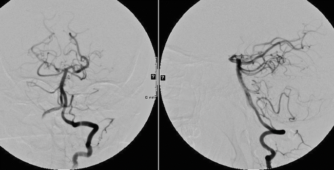
Cerebral angiogram, left, AP projection and, right, lateral projection, of a left VA injection displays the basilar artery and its branches after removal of the microcatheter and guide catheters. The aneurysm is completely occluded, and the posterior cerebral arteries are patent
-
12.
The guide catheters were removed after confirming no vascular injury to the vertebral and carotid arteries.
-
13.
The femoral artery sheaths were removed bilaterally with an Angio-Seal device used for arteriotomy closure.


Postprocedure Course
The patient was admitted to the neurosurgical intensive care unit for postprocedure monitoring. Approximately 16 h after the conclusion of the procedure, she was found to have a right visual field deficit. A CT angiogram confirmed patency of the stent and posterior cerebral vasculature. Magnetic resonance imaging confirmed emboliform infarction within the left posterior cerebral artery distribution. An eptifibatide infusion (2 mcg/kg/min) was commenced and continued for 24 h, with gradual resolution of symptoms [18]. She was discharged home on postprocedure day 4 at her neurological baseline level. Dual antiplatelet medication was continued for 12 months after the procedure.
Discussion
A wide-necked bifurcation aneurysm presents a difficult problem for endovascular treatment. Such an aneurysm is best treated with stent reconstruction of the aneurysm neck prior to coil embolization. At this point, there is no flow-diversion device available for use in treatment of a bifurcation aneurysm. Due to the morphology of an arterial bifurcation, this frequently requires placement of two stents in a “Y” configuration [19]. In this case, due to a widely patent posterior communicating artery on the right, a combined anterior–posterior approach was planned. With this construct, one stent could be placed rather than two, limiting the number of implants required to reconstruct the aneurysm neck. With a stent–coiling technique, two microcatheters are required. This may be performed through a single large femoral sheath, although bilateral access simplifies the procedure. In this case, the combined anterior–posterior approach required two guide catheters.
In conjunction with treatment of bifurcation aneurysm with stent reconstruction, thromboembolism is a postoperative risk. In this case, an absence of hemorrhage makes a small thromboembolic event a likely explanation of the postoperative field cut. An eptifibatide infusion was commenced in an effort to treat the suspected thromboembolism. This represents an off-label use of this platelet glycoprotein IIb/IIIa receptor inhibitor, which may have some clot-dissolution ability. As is very commonly noted in clinical practice, glycoprotein IIb/IIIa inhibitors rapidly reverse the effects of iatrogenic minor thromboembolic events [20].
Case 4
Flow-Diversion Treatment of Wide-Necked Aneurysm
Clinical Presentation
A 66-year-old woman presented with left eye visual loss. Noninvasive imaging revealed a 2 cm left ophthalmic artery aneurysm. Treatment with a flow-diversion device was planned. A general concern in treatment of this aneurysm with a flow-diversion device is trapping the ophthalmic artery. In our experience, the ophthalmic artery is sufficiently robust as well as routinely supplied by external carotid anastomoses such that it is not compromised after treatment with the PED. Dual antiplatelet therapy with aspirin and clopidogrel was started 1 week prior to the procedure.
Procedure Description
-
1.
Standard right femoral artery access with a 6 F sheath was obtained, confirming a giant (>25 mm) ophthalmic artery aneurysm (Fig. 5.24).
Fig. 5.24 
Cerebral angiogram, left, AP projection and, right, lateral projection, of a left ICA injection displays a giant aneurysm of the ICA (giant ophthalmic artery aneurysm)
-
2.
After diagnostic angiography confirmed the aneurysm, the diagnostic catheter was removed.
-
3.
A 6 F Envoy guiding catheter was advanced over a 0.035 in. guidewire into the aortic arch, where the left ICA was selectively catheterized with the aid of direct fluoroscopic inspection. With positioning of the guiding catheter within the distal cervical ICA, significant vessel spasm developed, necessitating treatment.
-
4.
The guiding catheter was retracted to a proximal position in the ICA, and 10 mg of verapamil was slowly infused directly to the affected vessel. After a delay of 5 min, there was significant improvement in vessel spasm.
-
5.
After resolution of the vessel spasm, the guiding catheter was advanced to a nonocclusive position in the distal cervical ICA.
-
6.
A suitable working angle to delineate relevant anatomic features of the aneurysm was selected (Fig. 5.25).
Fig. 5.25 
Working views for treatment of basilar terminus aneurysm from 3D angiogram reconstruction. Clear views (left, AP view; right, lateral view) of the parent vessel (the ICA) and the aneurysm neck allow safe coil embolization
-
7.
Under roadmap guidance, a Marksman microcatheter (ev3/Covidien) was directed past the aneurysm over a weighted-tip microwire (angled-tip Guidewire M Gold [Terumo Interventional Systems]) into the MCA (Fig. 5.26). This microcatheter has sufficient inner diameter to allow for passage and delivery of the PED.
Fig. 5.26 
Cerebral angiogram, left, AP projection and, right, lateral projection, of a left ICA injection displays working views for placement of a flow-diverting stent based on the working views developed from the 3D angiogram. The Marksman catheter (ev3) has been navigated through the aneurysm into a distal position in the MCA
-
8.
With the microcatheter in suitable position distal to the aneurysm, the microwire was removed and the PED advanced into position through the microcatheter.
-
9.
After confirming placement of the PED proximal to the posterior communicating artery, the PED was deployed into position. The PED is initially deployed by rotating the accompanying microwire clockwise to release the distal end. The device is then unsheathed using alternating pushing and pulling motions to oppose the edge of the stent to the vessel wall, as the device has very little radial force. Care must be taken to carefully measure and place the device to avoid covering small perforating vessels. The device is sized to approximate the diameter of the parent vessel.
-
10.
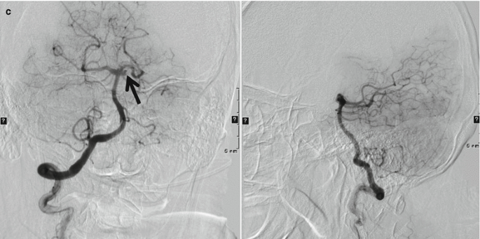
Once the device was placed, angiographic runs displayed stasis of flow within the aneurysm (Fig. 5.27). Subsequent runs completed several minutes after deployment displayed progression of intra-aneurysmal flow stasis (Fig. 5.28).
Fig. 5.27 

Intraoperative cerebral angiogram, left, AP projection and, right, lateral projection, of a left ICA injection immediately following placement of PED. Early (a), middle (b), and late (c) phases of this angiogram display stasis of contrast material within the aneurysm
Fig. 5.28 

Intraoperative cerebral angiogram, left, AP projection and, right, lateral projection, of a left ICA injection 7 min following placement of PED. Early (a), middle (b), and late (c) phases of this angiogram display less filling of the aneurysm due to flow diversion, with increased stasis of contrast material in the aneurysm
-
11.
With the flow-diversion device in place, the catheters were removed and the arteriotomy closed with manual pressure.


Postprocedure Course
The patient was admitted to the neurosurgical intensive care unit for routine monitoring without incident. Dual antiplatelet therapy was to be continued for 1 year. Angiography performed 3 months after placement of the PED revealed no residual aneurysm and patency of the ophthalmic artery (Fig. 5.29).

Cerebral angiogram, left, AP projection and, right, lateral projection, of a left common carotid artery injection displays complete obliteration of the aneurysm and endoluminal reconstruction of the ICA 6 months after placement of the PED
Discussion
The PED is unforgiving in its delivery. It must be positioned carefully to avoid covering important perforating vessels, and its limited outward radial force necessitates a pushing movement after partial unsheathing for proper vessel wall apposition. This maneuver may cause a twisting or intussusceptions of the stent, which may be difficult to reverse. In the Pipeline for Uncoilable or Failed Aneurysms Study (PUFS), delivery was successful for 98 % of 107 patients treated [21]. Treatment of large anterior circulation aneurysms with the PED has proven to be a safe and effective treatment, with 82 % complete occlusion at 180 days after treatment with a 6 % major complication rate. Alternative endovascular treatments for large wide-necked aneurysms include stent reconstruction (similar to that described in Case 3) or parent vessel occlusion [22]. However, the reported recurrence/residual rates appear to be lower for PED as compared with stent-assisted coiling for wide-necked large and giant aneurysms [23–30].
Conclusion
Treatment of intracranial aneurysm is determined principally on the basis of anatomical considerations and morphology. Anatomical and clinical characteristics must be taken into consideration with endovascular treatment of intracranial aneurysm. A good understanding of the aneurysm anatomy will enable successful treatment and minimize complications. Although hardly a conclusive review of endovascular techniques in treatment of aneurysm, the cases here present basic techniques, including coil embolization, aneurysm neck reconstruction, and flow diversion.
Abbreviations
- 3D:
-
Three dimensional
- ACT:
-
Activated coagulation time
- AP:
-
Anteroposterior
- F:
-
French
- FDA:
-
Food and Drug Administration
- ICA:
-
Internal carotid artery
- ISUIA:
-
International Study of Unruptured Intracranial Aneurysms
- MCA:
-
Middle cerebral artery
- PED:
-
Pipeline embolization device
- PUFS:
-
Pipeline for Uncoilable or Failed Aneurysms Study
- SAH:
-
Subarachnoid hemorrhage
- VA:
-
Vertebral artery
References
Molyneux AJ, Kerr RS, Yu LM, Clarke M, Sneade M, Yarnold JA, et al. International subarachnoid aneurysm trial (ISAT) of neurosurgical clipping versus endovascular coiling in 2143 patients with ruptured intracranial aneurysms: a randomised comparison of effects on survival, dependency, seizures, rebleeding, subgroups, and aneurysm occlusion. Lancet. 2005;366:809–17.
McDougall CG, Spetzler RF, Zabramski JM, Partovi S, Hills NK, Nakaji P, et al. The barrow ruptured aneurysm trial. J Neurosurg. 2012;116:135–44.
Alshekhlee A, Mehta S, Edgell RC, Vora N, Feen E, Mohammadi A, et al. Hospital mortality and complications of electively clipped or coiled unruptured intracranial aneurysm. Stroke. 2010;41:1471–6.
Koebbe CJ, Veznedaroglu E, Jabbour P, Rosenwasser RH. Endovascular management of intracranial aneurysms: current experience and future advances. Neurosurgery. 2006;59:S93–102; discussion S103–13.
Chen PR, Frerichs K, Spetzler R. Current treatment options for unruptured intracranial aneurysms. Neurosurg Focus. 2004;17:E5.
Origitano TC. Current options in clipping versus coiling of intracranial aneurysms: to clip, to coil, to wait and watch. Neurosurg Clin N Am. 2008;19:469–76, vi.
Hunt WE, Hess RM. Surgical risk as related to time of intervention in the repair of intracranial aneurysms. J Neurosurg. 1968;28:14–20.
Hunt WE, Kosnik EJ. Timing and perioperative care in intracranial aneurysm surgery. Clin Neurosurg. 1974;21:79–89.
Rahman M, Smietana J, Hauck E, Hoh B, Hopkins N, Siddiqui A, et al. Size ratio correlates with intracranial aneurysm rupture status: a prospective study. Stroke. 2010;41:916–20.
Wiebers DO, Whisnant JP, Huston 3rd J, Meissner I, Brown Jr RD, Piepgras DG, et al. Unruptured intracranial aneurysms: natural history, clinical outcome, and risks of surgical and endovascular treatment. Lancet. 2003;362:103–10.
Ogilvy CS, Yang X, Jamil OA, Hauck EF, Hopkins LN, Siddiqui AH, et al. Neurointerventional procedures for unruptured intracranial aneurysms under procedural sedation and local anesthesia: a large-volume, single-center experience. J Neurosurg. 2011;114:120–8.
Guglielmi G, Vinuela F, Dion J, Duckwiler G. Electrothrombosis of saccular aneurysms via endovascular approach. Part 2: preliminary clinical experience. J Neurosurg. 1991;75:8–14.
Moret J, Cognard C, Weill A, Castaings L, Rey A. Reconstruction technic in the treatment of wide-neck intracranial aneurysms. Long-term angiographic and clinical results. Apropos of 56 cases. J Neuroradiol. 1997;24:30–44.
Mawad ME, Klucznik RP, Ciceri EF. Endovascular treatment of cerebral aneurysms with the liquid polymer Onyx: initial clinical experience. In: Presented at 39th annual meeting of the American Society of Neuroradiology, Boston, MA; 23–27 Apr 2001.
Mericle RA, Lanzino G, Wakhloo AK, Guterman LR, Hopkins LN. Stenting and secondary coiling of intracranial internal carotid artery aneurysm: technical case report. Neurosurgery. 1998;43:1229–34.
Kallmes DF, Ding YH, Dai D, Kadirvel R, Lewis DA, Cloft HJ. A new endoluminal, flow-disrupting device for treatment of saccular aneurysms. Stroke. 2007;38:2346–52.
Fisher CM, Kistler JP, Davis JM. Relation of cerebral vasospasm to subarachnoid hemorrhage visualized by computerized tomographic scanning. Neurosurgery. 1980;6:1–9.
Memon MZ, Natarajan SK, Sharma J, Mathews MS, Snyder KV, Siddiqui AH, et al. Safety and feasibility of intraarterial eptifibatide as a revascularization tool in acute ischemic stroke. J Neurosurg. 2011;114:1008–13.
Chow MM, Woo HH, Masaryk TJ, Rasmussen PA. A novel endovascular treatment of a wide-necked basilar apex aneurysm by using a Y-configuration, double-stent technique. AJNR Am J Neuroradiol. 2004;25:509–12.
Dumont TM, Kan P, Snyder KV, Hopkins LN, Siddiqui AH, Levy EI. Adjunctive use of eptifibatide for complication management during elective neuroendovascular procedures. J Neurointerv Surg. 2013;5:226–30.
U.S. Food and Drug Administration. Pipeline embolization device – P100018. Summary of safety and effectiveness data (SSED). Issued 6 Apr 2011. http://www.accessdata.fda.gov/cdrh_docs/pdf10/P100018b.pdf. Accessed 3 Feb 2012.
Gonzalez NR, Duckwiler G, Jahan R, Murayama Y, Vinuela F. Challenges in the endovascular treatment of giant intracranial aneurysms. Neurosurgery. 2008;62:1324–35.
Benitez RP, Silva MT, Klem J, Veznedaroglu E, Rosenwasser RH. Endovascular occlusion of wide-necked aneurysms with a new intracranial microstent (Neuroform) and detachable coils. Neurosurgery. 2004;54:1359–68.
Gao X, Liang G, Li Z, Wei X, Cao P. A single-centre experience and follow-up of patients with endovascular coiling of large and giant intracranial aneurysms with parent artery preservation. J Clin Neurosci. 2012;19:364–9.
Liang G, Gao X, Li Z, Wei X, Xue H. Neuroform stent-assisted coiling of intracranial aneurysms: a 5 year single-center experience and follow-up. Neurol Res. 2010;32:721–7.
Lylyk P, Miranda C, Ceratto R, Ferrario A, Scrivano E, Luna HR, et al. Curative endovascular reconstruction of cerebral aneurysms with the pipeline embolization device: the Buenos Aires experience. Neurosurgery. 2009;64:632–42.
Nelson PK, Lylyk P, Szikora I, Wetzel SG, Wanke I, Fiorella D. The pipeline embolization device for the intracranial treatment of aneurysms trial. AJNR Am J Neuroradiol. 2011;32:34–40.
Szikora I, Berentei Z, Kulcsar Z, Marosfoi M, Vajda ZS, Lee W, et al. Treatment of intracranial aneurysms by functional reconstruction of the parent artery: the Budapest experience with the pipeline embolization device. AJNR Am J Neuroradiol. 2010;31:1139–47.
Tahtinen OI, Vanninen RL, Manninen HI, Rautio R, Haapanen A, Niskakangas T, et al. Wide-necked intracranial aneurysms: treatment with stent-assisted coil embolization during acute (<72 h) subarachnoid hemorrhage – experience in 61 consecutive patients. Radiology. 2009;253:199–208.
Weber W, Bendszus M, Kis B, Boulanger T, Solymosi L, Kuhne D. A new self-expanding nitinol stent (Enterprise) for the treatment of wide-necked intracranial aneurysms: initial clinical and angiographic results in 31 aneurysms. Neuroradiology. 2007;49:555–61.
Author information
Authors and Affiliations
Editor information
Editors and Affiliations
Rights and permissions
Copyright information
© 2014 Springer Science+Business Media New York
About this chapter
Cite this chapter
Dumont, T.M., Jahshan, S., Siddiqui, A.H. (2014). Endovascular Intracranial Aneurysm Treatment. In: Dieter, R., Dieter, Jr., R., Dieter, III, R. (eds) Endovascular Interventions. Springer, New York, NY. https://doi.org/10.1007/978-1-4614-7312-1_5
Download citation
DOI: https://doi.org/10.1007/978-1-4614-7312-1_5
Published:
Publisher Name: Springer, New York, NY
Print ISBN: 978-1-4614-7311-4
Online ISBN: 978-1-4614-7312-1
eBook Packages: MedicineMedicine (R0)